Shock absorber

a technology of shock absorber and shock absorber, which is applied in the direction of shock absorber, vibration damper, spring/damper, etc., can solve the problems of reducing the capacity of the reservoir, limiting space and layout, and increasing manufacturing costs, and achieves the effect of sufficient reservoir capacity

Inactive Publication Date: 2009-02-12
HITACHI LTD
View PDF4 Cites 50 Cited by
  • Summary
  • Abstract
  • Description
  • Claims
  • Application Information

AI Technical Summary

Benefits of technology

[0021]With the shock absorber according to the invention, during the extension stroke of the piston rod, the fluid flows from one of the cylinder chambers, passes through the extension-side passage, and flows into the other cylinder chamber via the extension-side damping valve and the extension-side check valve. At this time, the fluid in an amount corresponding to recession of the piston rod from the interior of the cylinder flows from the reservoir to the other cylinder chamber via the hollow rod, the inside of the piston rod, the connecting path, the extension-side passage, and the extension-side check valve to compensate for the change in capacity of the cylinder. During the compression...

Problems solved by technology

However, the above-described conventional hydraulic shock absorber-provided with the reservoir in the pis...

Method used


Image

  • Shock absorber
  • Shock absorber
  • Shock absorber

Examples


first embodiment

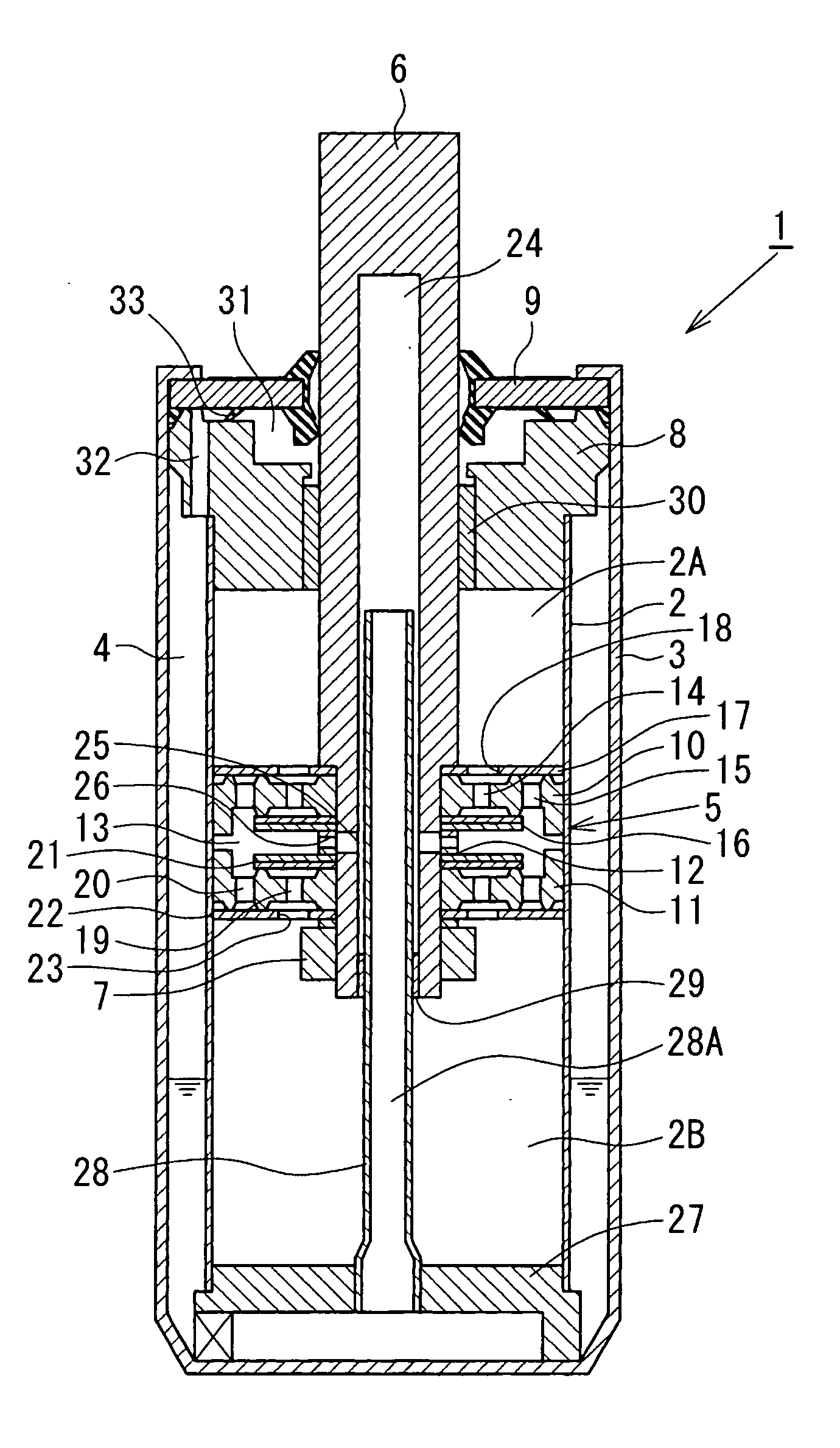
[0038]the invention will be described with reference to FIG. 1. As shown in FIG. 1, a shock absorber 1 according to the present embodiment is a tube type hydraulic shock absorber having a double tube structure including an outer tube substantially in a shape of a bottomed cylinder and provided to an outer periphery of a cylinder 2 and an annular reservoir 4 formed between the cylinder 2 and the outer tube 3. A piston 5 is slidably fitted in the cylinder 2. The piston 5 divides an interior of the cylinder 2 into two chambers, i.e., a cylinder upper chamber 2A and a cylinder lower chamber 2B. A base end portion of a hollow piston rod 6 is coupled to the piston 5 by a nut 7 and the other end side of the piston rod 6 is inserted through a rod guide 8 and a rod seal 9 mounted to opening ends of the cylinder 2 and the outer tube 3 and extends outside. Oil (fluid) is filled in the cylinder 2 hermetically sealed with the rod guide 8 and the rod seal 9 and oil and gas (or the air) are filled...

second embodiment

[0064]Next, variations of the coupling structure of the partition wall member 27 and the hollow rod 28 of the second embodiment will be described with reference to FIGS. 9 and 10.

[0065]In the variation shown in FIG. 9, the partition wall member 27 is formed by pressing plates into a shape of a bottomed cylinder having a disk-shaped bottom portion 27A and a cylindrical side face portion 27B. The partition wall member 27 is fixed in the axial direction by crimping the side face portion 27B of the partition wall member 27 and the side wall of the cylinder 2 outward. Similarly to the variation shown in FIG. 5, the opening portion of the partition wall member 27 and the hollow rod 28 are tapered and fitted with each other and the tip end portion of the hollow rod 28 is crimped (diameter is increased) to thereby couple the partition wall member 27 and the hollow rod 28.

[0066]In the variation shown in FIG. 10, the partition wall member 27 and the hollow rod 28 are integrally formed by deep...


PUM


Abstract

A shock absorber includes a piston coupled to a hollow piston rod fitted in a cylinder and a reservoir disposed at an outer periphery portion of the cylinder. A rod chamber in the piston rod communicates with a piston chamber in the piston via a radial passage. A hollow rod fixed to a partition wall member is inserted into the piston rod and the rod chamber is connected to the reservoir by the hollow rod. An extension-side disk valve generates damping force during an extension stroke of the piston rod and a compression-side disk valve generates damping force during a compression stroke. Because the hollow rod connects the rod chamber to the reservoir at the outer periphery of the cylinder, it is possible to secure sufficient reservoir capacity.

Description

BACKGROUND OF THE INVENTION[0001]1. Field of the Invention[0002]The present invention relates to a shock absorber mounted on a suspension system or the like of a vehicle such as an automobile.[0003]2. Description of the Related Art[0004]In general, a tube type hydraulic shock absorber mounted on a suspension system of an automobile is formed by fitting a piston coupled to a piston rod into a cylinder filled with oil so that the piston can slide, and providing a damping force generating mechanism formed of an orifice, a disk valve, and the like in the piston. The damping force generating mechanism controls a flow of the oil generated by sliding of the piston in the cylinder caused by a stroke of the piston rod to thereby generate damping force. A reservoir filled with the oil and gas may be connected to a bottom portion of the cylinder with a base valve interposed therebetween, or alternatively, a free piston may be fitted in a bottom portion side of the cylinder to form a gas chambe...

Claims


Application Information

Patent Timeline
IPC IPC(8): F16F9/32
CPCF16F9/3482F16F9/063
Inventor MURAKAMI, HIROSHI
Owner HITACHI LTD
Why Eureka
Try Eureka