Compact fluorescent lamp

a fluorescent lamp and compact technology, applied in the field of compact fluorescent lamps, can solve the problems of limited success and usage, ineffective lighting of the room by itself, and the start of general lighting of l.e.d.s, and achieve the effect of reducing energy consumption

Inactive Publication Date: 2009-02-12
BOLTA CHARLES +1
View PDF5 Cites 0 Cited by
  • Summary
  • Abstract
  • Description
  • Claims
  • Application Information

AI Technical Summary

Benefits of technology

[0015]In an embodiment of the present invention, the switch means is a switch movable between illuminating the fluorescent tubing, illuminating the L.E.D., illuminating both the fluorescent tubing and the L.E.D., and turning off illumination of the fluorescent tubing and the L.E.D. The switch me

Problems solved by technology

Today L.E.D.s are starting to be used in general lighting with limited success and usage.
L.E.D. lighting by itself will not effectively luminate a room evenly and as fully as a compact fluorescent lamp, leaving dark areas 360 degrees away from the L.E.D. lighting.
Furthermore, the cost of a L.E.D. lamp for an equivalent amount of lumens from a compact fluorescent lamp is far more expensive than a compact fluorescent lamp lamp.
The photo-luminescent material absorbs light from the lighting in the room and when the ligh

Method used


Image

  • Compact fluorescent lamp
  • Compact fluorescent lamp
  • Compact fluorescent lamp

Examples


Embodiment Construction

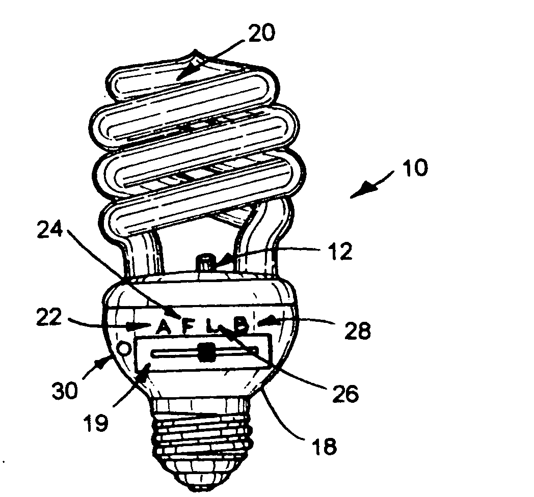
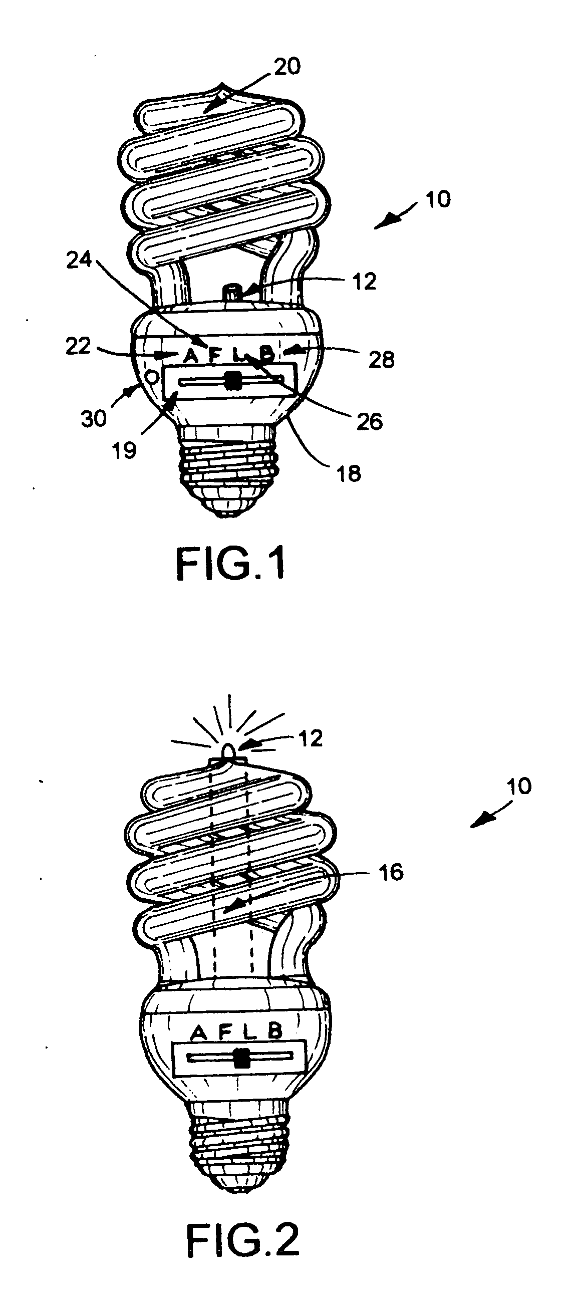
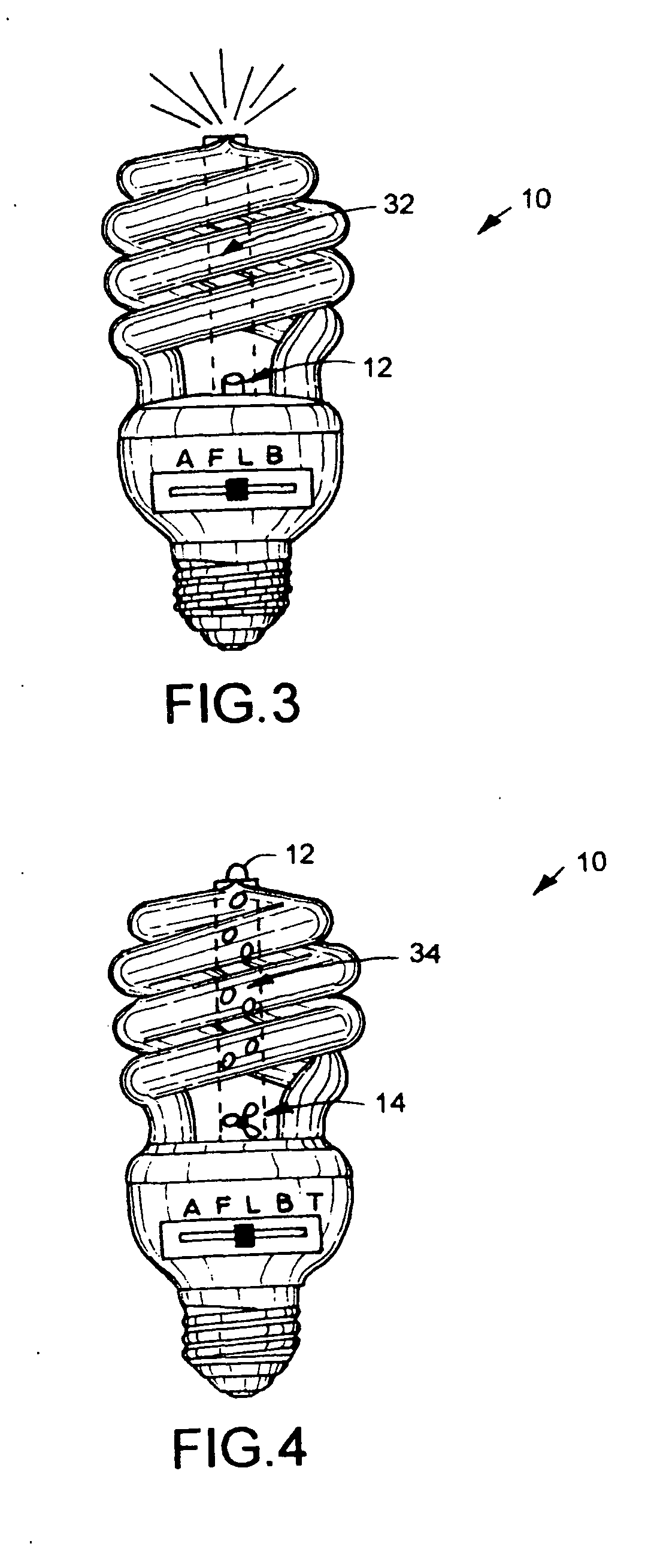
[0026]As illustrated in FIGS. 1-5, the present invention is a switchable compact fluorescent lamp, indicated generally at 10, with a light emitting diode (L.E.D.) 12 to maximize energy efficiency, an emergency backup L.E.D. light system, a fan 14 to cool the compact fluorescent lamp electronics and move air through the TiO2 coated fluorescent glass area, an afterglow pedestal L.E.D. mounting system 16 and plug imports for external power.

[0027]As illustrated in FIG. 1, a compact fluorescent lamp already starts off with lower usage of electricity than an incandescent lamp and with a switchable compact fluorescent lamp 10, as set forth in the present invention, with an added L.E.D. 12 system an even further reduction of energy usage can be achieved. The switchable compact fluorescent lamp 10 with an L.E.D. 12 added to the center of the top of the compact fluorescent lamp plastic electronic encasement housing 18 to maximize energy efficiency. Two different types of lamps, a compact fluo...


PUM


Abstract

A switchable compact fluorescent lamp with an L.E.D. added to the center of the top of the compact fluorescent lamp plastic electronic encasement housing. The L.E.D. can be switched on with the fluorescent on or switched to be on by itself with the fluorescent off. The lamp can also be switched to a battery and or capacitor power backup for the L.E.D. when the power goes off.

Description

[0001]The present application claims benefit of priority of pending provisional patent application Ser. No. 60 / 962,857, filed on Aug. 1, 2007, entitled “Afterglow Amplifier Emitter for Compact Fluorescent Lamps”.BACKGROUND OF THE INVENTION[0002]1. Field of the Invention[0003]The present invention relates generally to a compact fluorescent lamp and more particularly the invention relates to a switchable compact fluorescent lamp with a light emitting diode (L.E.D.) to maximize energy efficiency, an emergency backup L.E.D. light system, a fan to cool the compact fluorescent lamp electronics and move air through the TiO2 coated fluorescent glass area, an afterglow pedestal L.E.D. mounting system and plug imports for external power.[0004]2. Description of the Prior Art[0005]Compact fluorescent lamps are commonly found in essentially most residential and commercial buildings. Furthermore during this age of energy conservation the use of compact fluorescent lamps will be the common lamp us...

Claims


Application Information

Patent Timeline
IPC IPC(8): H05B35/00H01J9/00
CPCF21L4/00F21L4/02F21S9/022F21V29/02Y02B20/19F21Y2103/02F21Y2113/00F21Y2113/02H05B35/00F21Y2101/02F21Y2101/00F21V29/67F21Y2103/30F21Y2113/20F21Y2115/10Y02B20/00
Inventor BOLTA, CHARLESCLARK, DENNIS
Owner BOLTA CHARLES
Why Eureka
Try Eureka