Balun transformer

a transformer and transformer technology, applied in the field of balun transformers, can solve the problems of energy loss, weakening of electromagnetic coupling between couplers, etc., and achieve the effect of increasing the strength of electromagnetic coupling and reducing energy loss

Inactive Publication Date: 2009-02-12
SAMSUNG ELECTRO MECHANICS CO LTD
View PDF6 Cites 30 Cited by
  • Summary
  • Abstract
  • Description
  • Claims
  • Application Information

AI Technical Summary

Benefits of technology

[0010]An aspect of the present invention provides a balun transformer which can compensate for characteristic changes thereof and reduce energy loss by increasing the strength of electromagnetic coupling between couplers.

Problems solved by technology

Also, the electronic coupling between couplers decreases in strength, causing energy loss.

Method used


Image

  • Balun transformer
  • Balun transformer
  • Balun transformer

Examples


Embodiment Construction

[0024]Exemplary embodiments of the present invention will now be described in detail with reference to the accompanying drawings.

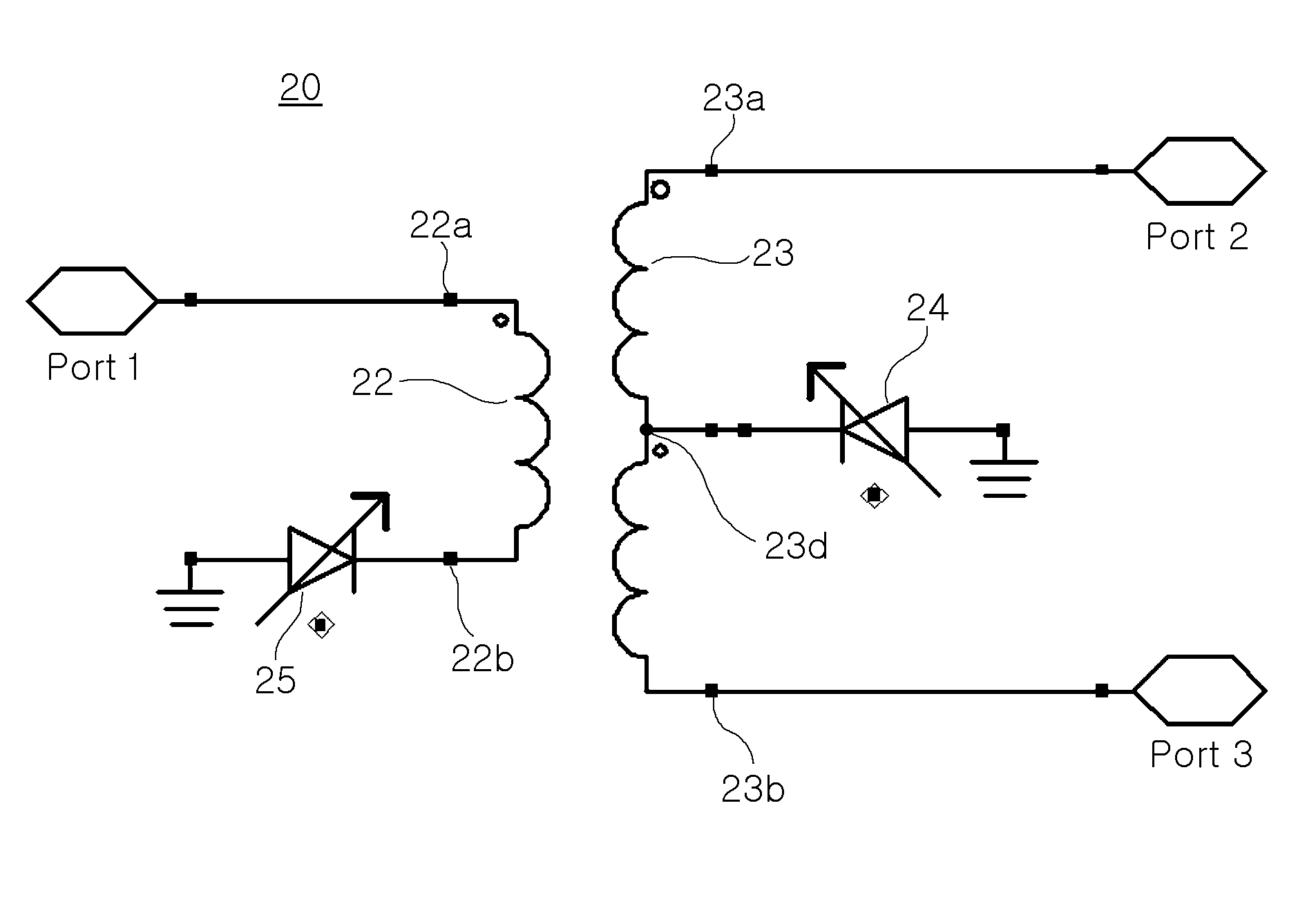
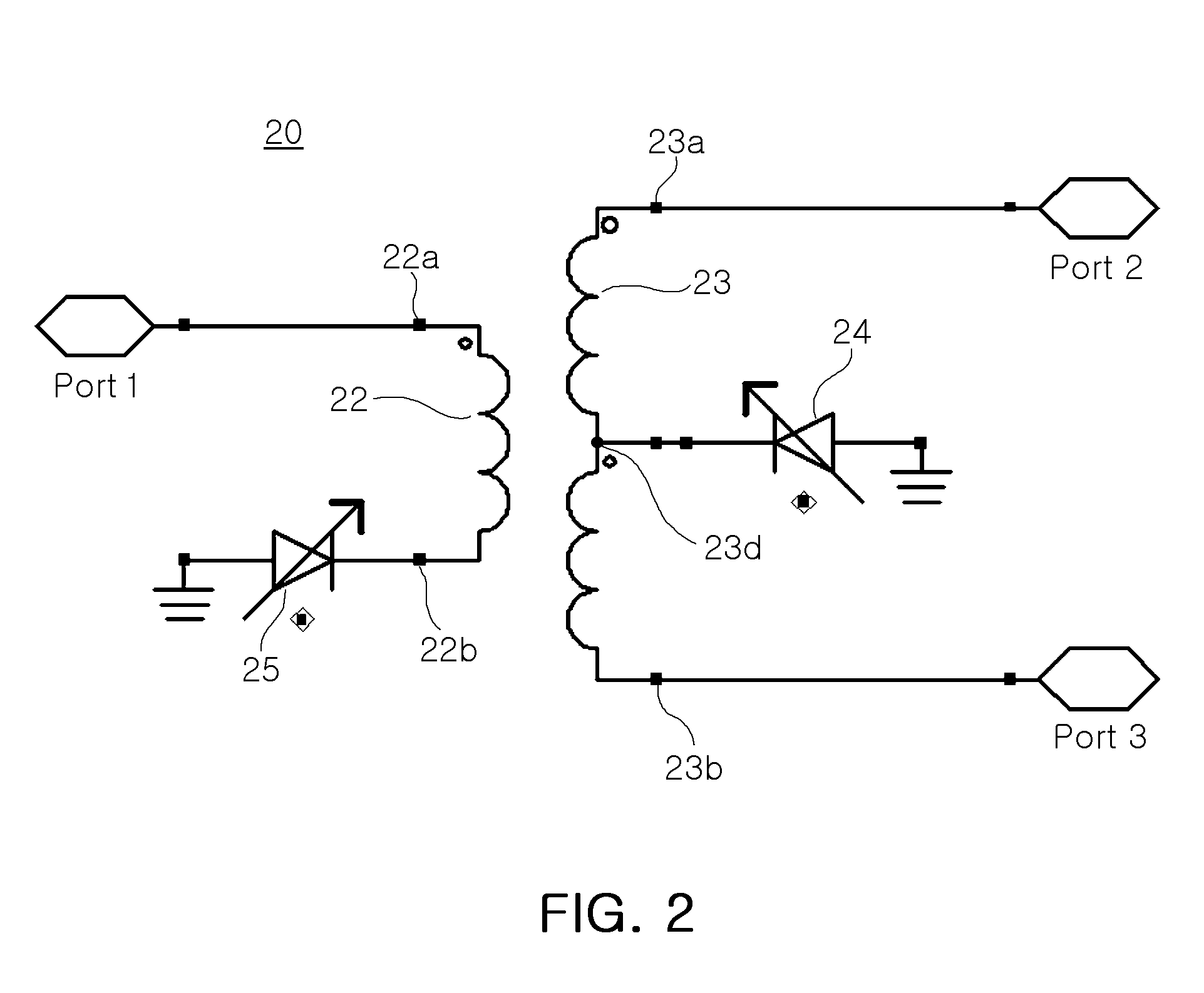
[0025]FIG. 2 is an equivalent circuit diagram of a balun transformer according to an exemplary embodiment of the present invention.

[0026]Referring to FIG. 2, a balun transformer 20 according to the current embodiment includes a first conductive pattern 22, a second conductive pattern 23, a first variable capacitor 24 and a second variable capacitor 25.

[0027]A middle part 23d of an electrical length of the second conductive pattern 23 may be connected to a ground part so that both ends of the second conductive patter 23 are used as input / output ports of a balanced signal. According to the current embodiment, the first variable capacitor 24 may be connected between the middle part 23d and the ground part.

[0028]The first conductive pattern 22 and the second conductive pattern 23 are electromagnetically coupled to each other. Thus, when an unbalanced signal is...


PUM


Abstract

A balun transformer includes a first conductive pattern having one end provided as an input/output port of an unbalanced signal, a second conductive pattern electromagnetically coupled to the first conductive pattern and having both ends provided as input/output ports of a balanced signal, and a first variable capacitor connected between a ground part and a middle part of an electrical length of the second conductive pattern.

Description

CROSS-REFERENCE TO RELATED APPLICATIONS[0001]This application claims the priority of Korean Patent Application No. 2007-79036 filed on Aug. 7, 2007, in the Korean Intellectual Property Office, the disclosure of which is incorporated herein by reference.BACKGROUND OF THE INVENTION[0002]1. Field of the Invention[0003]The present invention relates to a balun transformer, and more particularly, to a balun transformer which can facilitate control of characteristics thereof according to an external condition and reduce energy loss by increasing the strength of electromagnetic coupling.[0004]2. Description of the Related Art[0005]The term ‘balun’ of a balun transformer is short for balance-unbalance. The balun transformer refers to a device that includes a circuit or a structure for converting a balanced signal to an unbalanced signal or vice versa. When a device including a balanced input / output port such as a mixer or an amplifier is connected with a device including an unbalanced input / ...

Claims


Application Information

Patent Timeline
Patent Type & Authority Applications(United States)
IPC IPC(8): H03H5/00
CPCH03H7/42H03H7/0153H03H2001/0085H01P5/10H01F17/02
Inventor LEE, KWANG DUKIM, YU SINKIM, JEONG HOONKIM, EUNG JUJEONG, MOON SUKPARK, SANG GYUHAN, DONG OK
Owner SAMSUNG ELECTRO MECHANICS CO LTD
Why Eureka
Try Eureka