Illumination device having unidirectional heat-dissipating route

a technology of heat dissipation route and illumination device, which is applied in the direction of semiconductor devices for light sources, lighting and heating equipment, lighting support devices, etc., can solve the problem of reducing the working life of leds

Inactive Publication Date: 2009-02-12
AMA PRECISION INC
View PDF9 Cites 70 Cited by
  • Summary
  • Abstract
  • Description
  • Claims
  • Application Information

AI Technical Summary

Problems solved by technology

Therefore, the LEDs are heated to be generally in the high temperature environment, such that the working life of the LEDs are decreased greatly.

Method used


Image

  • Illumination device having unidirectional heat-dissipating route
  • Illumination device having unidirectional heat-dissipating route
  • Illumination device having unidirectional heat-dissipating route

Examples


Embodiment Construction

[0014]Reference will now be made to the drawings to describe exemplary embodiments of the present illumination device, in detail. The following description is given by way of example, and not limitation.

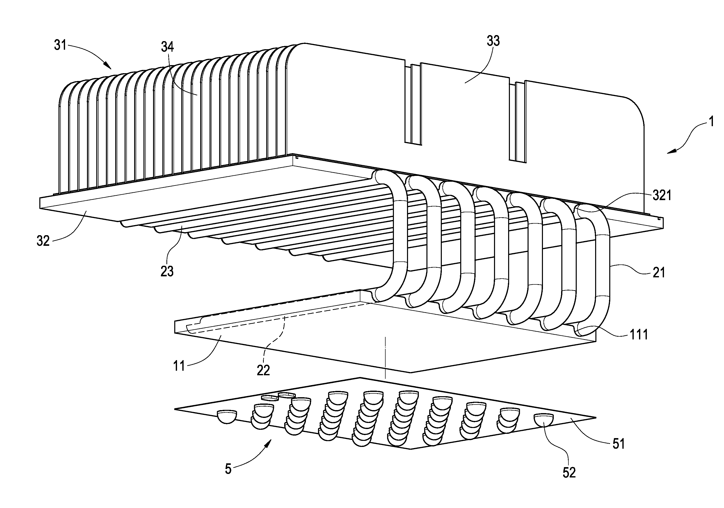
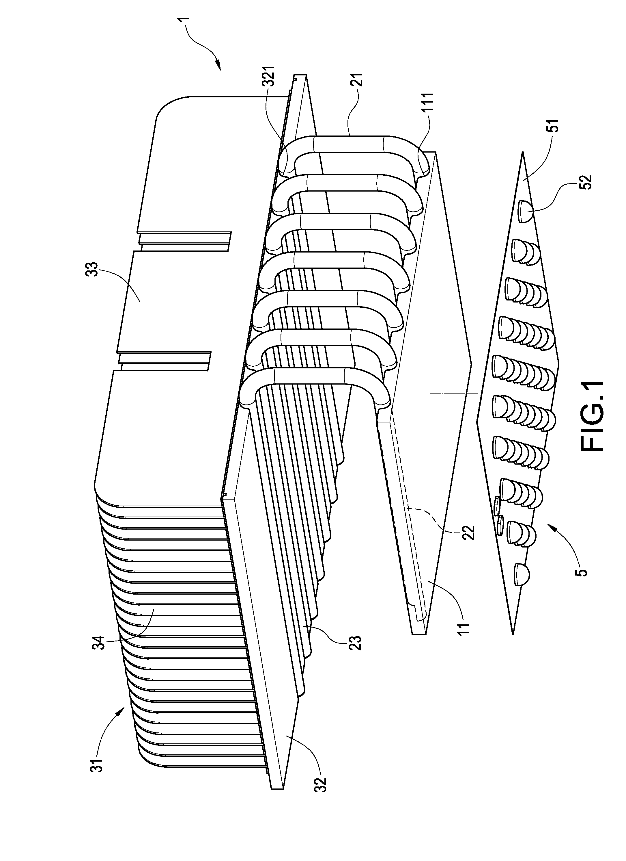
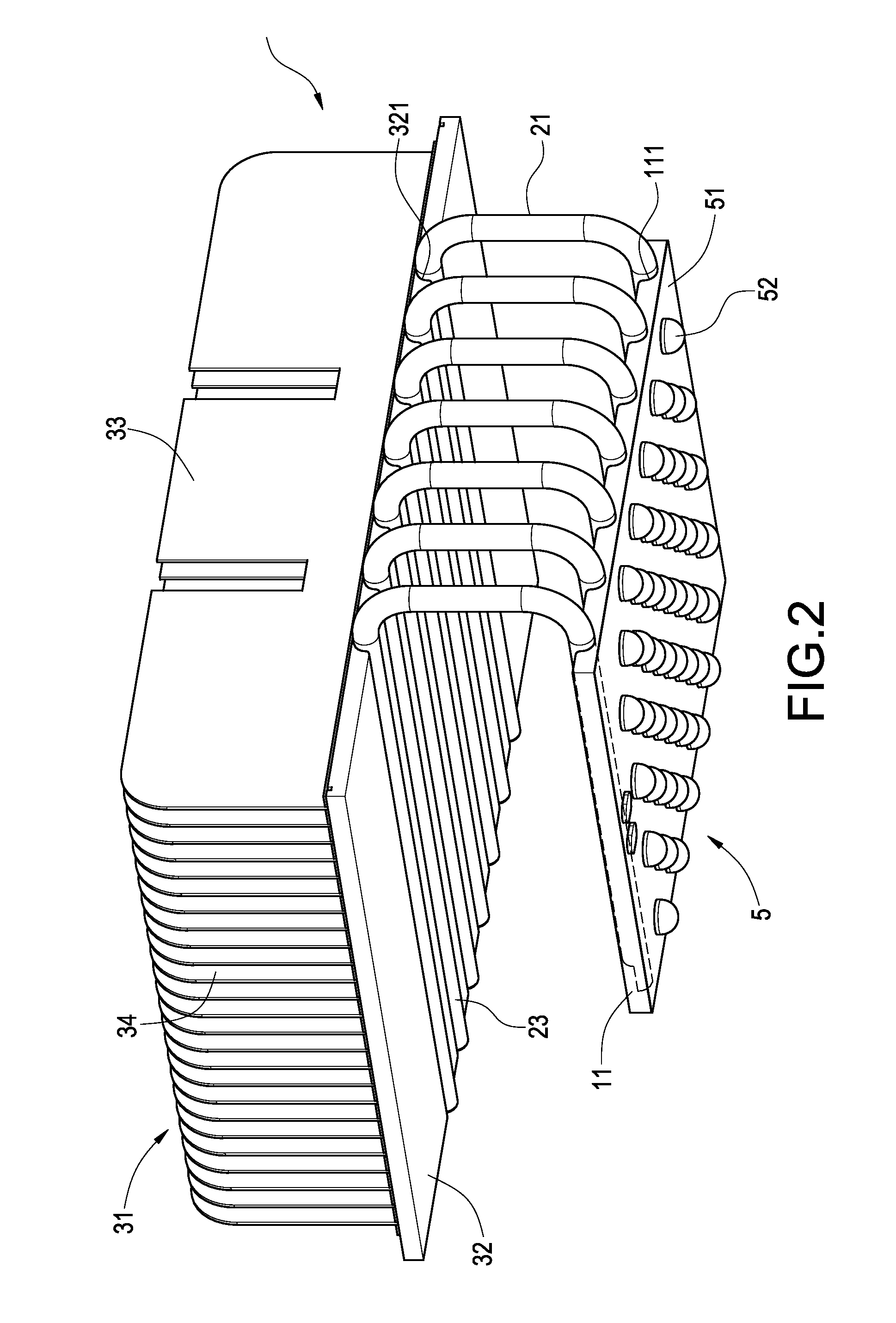
[0015]Referring to FIGS. 1 and 2, an isometric exploded view and an isometric assembled view of a heat sink and a LED light module in accordance with an exemplary embodiment of the present invention, are provided. The present invention relates to an illumination device having an unidirectional heat-dissipating route. The illumination device mainly includes a heat sink 1 and a LED light module 5.

[0016]The heat sink 1 includes a heat plate 11, one or at least one heat pipe 21 and a heat dissipating body 31. The heat plate 11 is made of aluminum, copper or other material with high heat-conducting capability. A plurality of grooves 111 are formed in a top surface of the heat plate 11, and the grooves 111 are parallel to each other.

[0017]The amount of the heat pipe 21 may be changed accor...


PUM


Abstract

An illumination device having an unidirectional heat-dissipating route, includes a heat sink and a LED light module. The heat sink includes a heat plate, a heat pipe and a heat-dissipating body. The heat pipe has a heat absorbing portion and a heat dissipating portion with a horizontal position different to that of the heat absorbing portion. The heat absorbing portion is connected to the heat plate, and a plurality of grooves is formed in the heat pipe to be communicated with the heat absorbing portion and the heat dissipating portion. The heat absorbing portion is lower than the heat dissipating portion. The heat-dissipating body is connected to the heat dissipating portion. The LED light module is connected to the heat plate. Thus the LEDs are protected and prevented from being destroyed by the heat, and the working life thereof is increased greatly.

Description

BACKGROUND[0001]1. Field of the Invention[0002]The present invention relates to an illumination device, and more particularly, to an illumination device suitable in the high temperature environment.[0003]2. Description of the Related Art[0004]LED (light emitting diode) has many advantages, such as excellent luminance, long life, lower power-consumption, etc, such that it has been used widely in indoor or outdoor illumination devices. However, the LED should be operated in a suitable temperature working-environment, which relates directly to the working-life of the LED. Therefore, the present invention is to focus on the heat-dissipating capability of the illumination device.[0005]A conventional illumination device, as disclosed in the Taiwan Patent No. M309053, forms an insulating layer and a printed circuit on a bottom surface of a metal substrate for being electrically connected to a plurality of LEDs. The LED illumination device is designed that heat absorbing portions of heat pi...

Claims


Application Information

Patent Timeline
Patent Type & Authority Applications(United States)
IPC IPC(8): F21V29/02F21V21/00
CPCF21V29/004F21V29/763F21Y2101/02F21V29/006F21V29/71F21V29/74F21V29/89F21Y2115/10F21Y2105/10
Inventor CHEN, KUO-HSINLIN, HSUAN-CHIH
Owner AMA PRECISION INC
Why Eureka
Try Eureka