Selecting Delay Values for a RAKE Receiver

a delay value and receiver technology, applied in the direction of digital transmission, amplitude demodulation, electrical apparatus, etc., can solve the problems of fading, significant decrease of path gain, interference in the receiver, etc., and achieve the effect of reducing current consumption and dye area, and sufficiently high resolution for the rak

Active Publication Date: 2009-02-12
TELEFON AB LM ERICSSON (PUBL)
View PDF7 Cites 6 Cited by
  • Summary
  • Abstract
  • Description
  • Claims
  • Application Information

AI Technical Summary

Benefits of technology

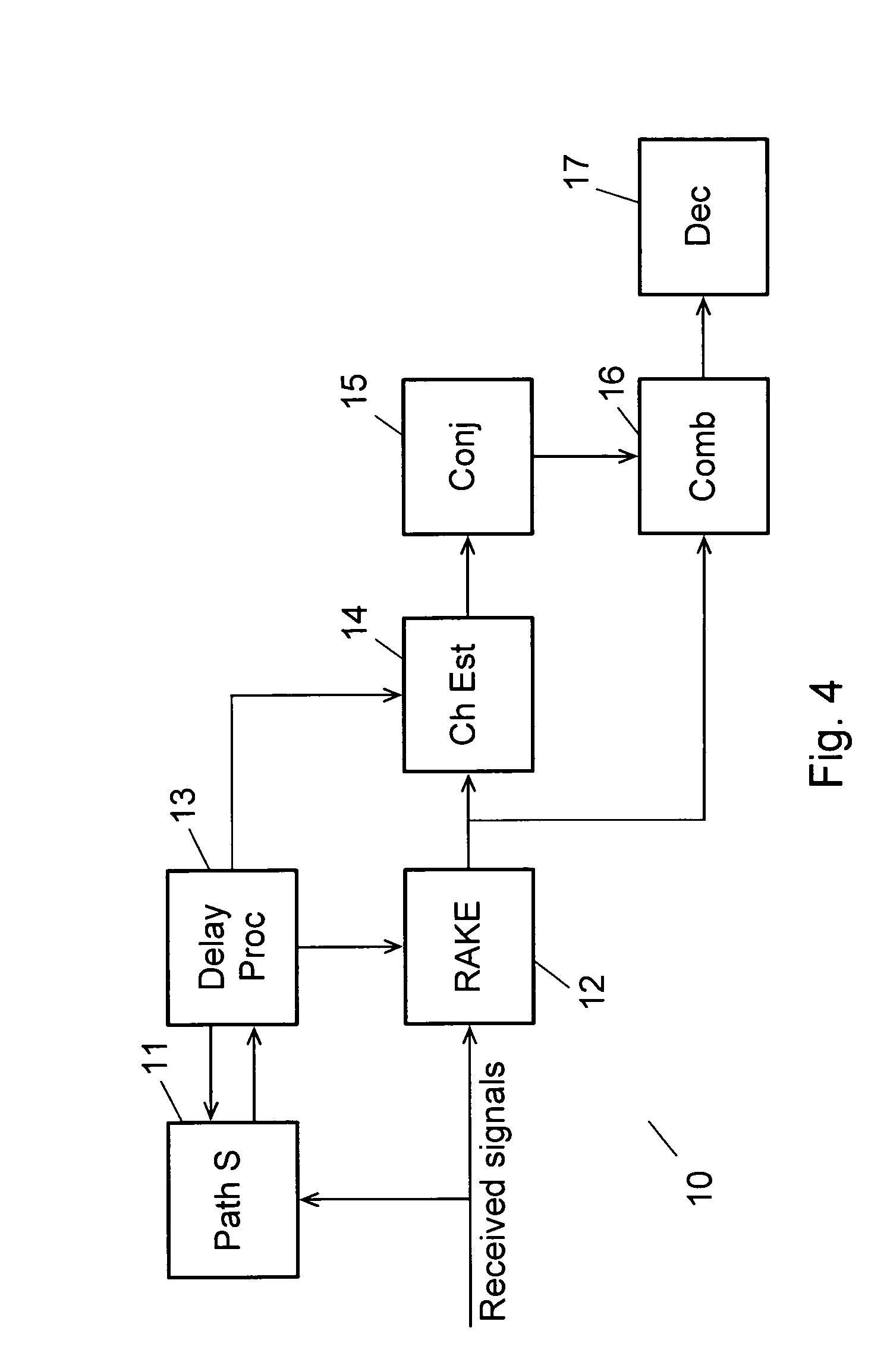
[0020]By using interpolation for estimating intermediate signal levels, a resolution that is sufficient for the RAKE can be achieved from the wide path search in a relatively simple way without increasing the current consumption or the dye area required for despreaders. Thus this method only relies upon the wide search for finding and monitoring the propagation channel time delays and selecting the time delays for despreading data in the RAKE.
[0038]Further, the receiver may be arranged to provide in response to an activated path search for a transmitter a new search delay profile for that transmitter, and in that case the receiver may further be arranged to extract the delay values of a number of the largest peaks and their closest neighbour delay values of said new search delay profile for a transmitter; and update a previous delay profile provided for that transmitter by calculating for each delay value represented in the previous delay profile as well as in the extracted delay values an updated magnitude of received signal level for that delay value by adding to the previously calculated magnitude a percentage of the difference between the previously calculated magnitude and the corresponding magnitude from the new search delay profile, thereby obtaining an updated delay profile. By updating the previous delay profile in view of the new search delay profile instead of just using the new search delay profile, it is ensured that short noise peaks do not change the profile too much.

Problems solved by technology

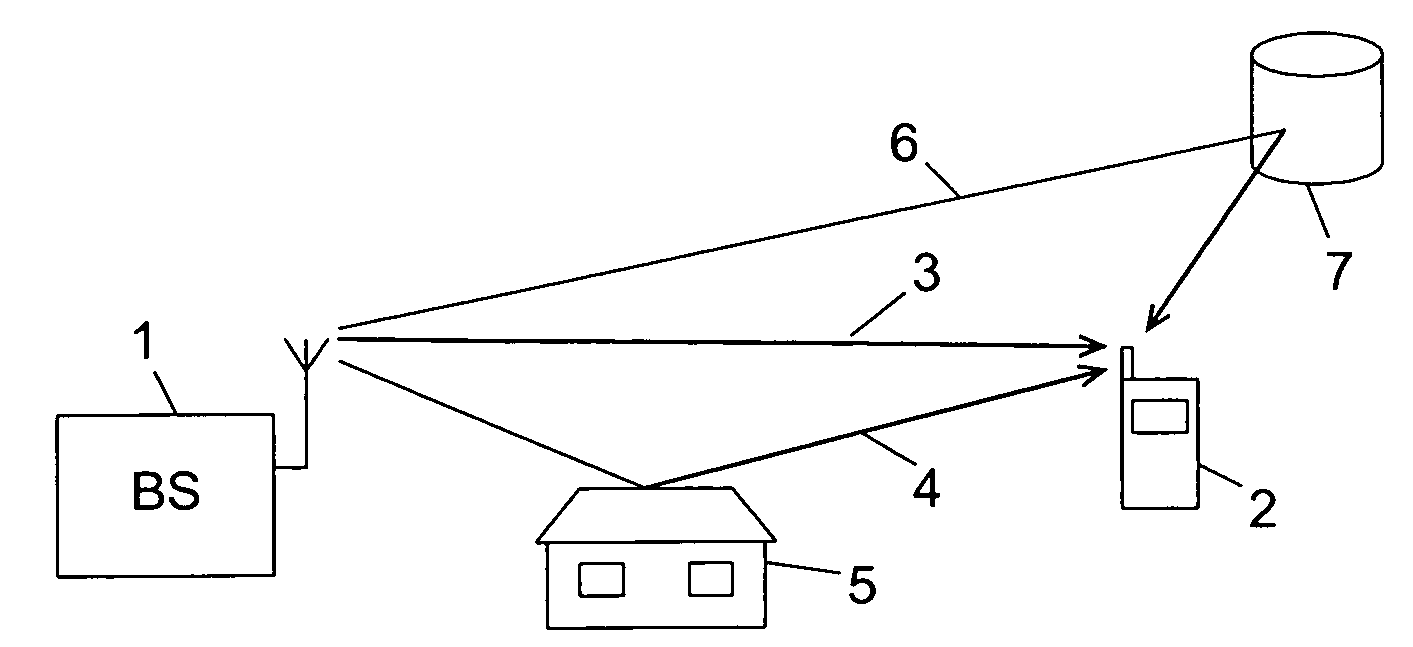
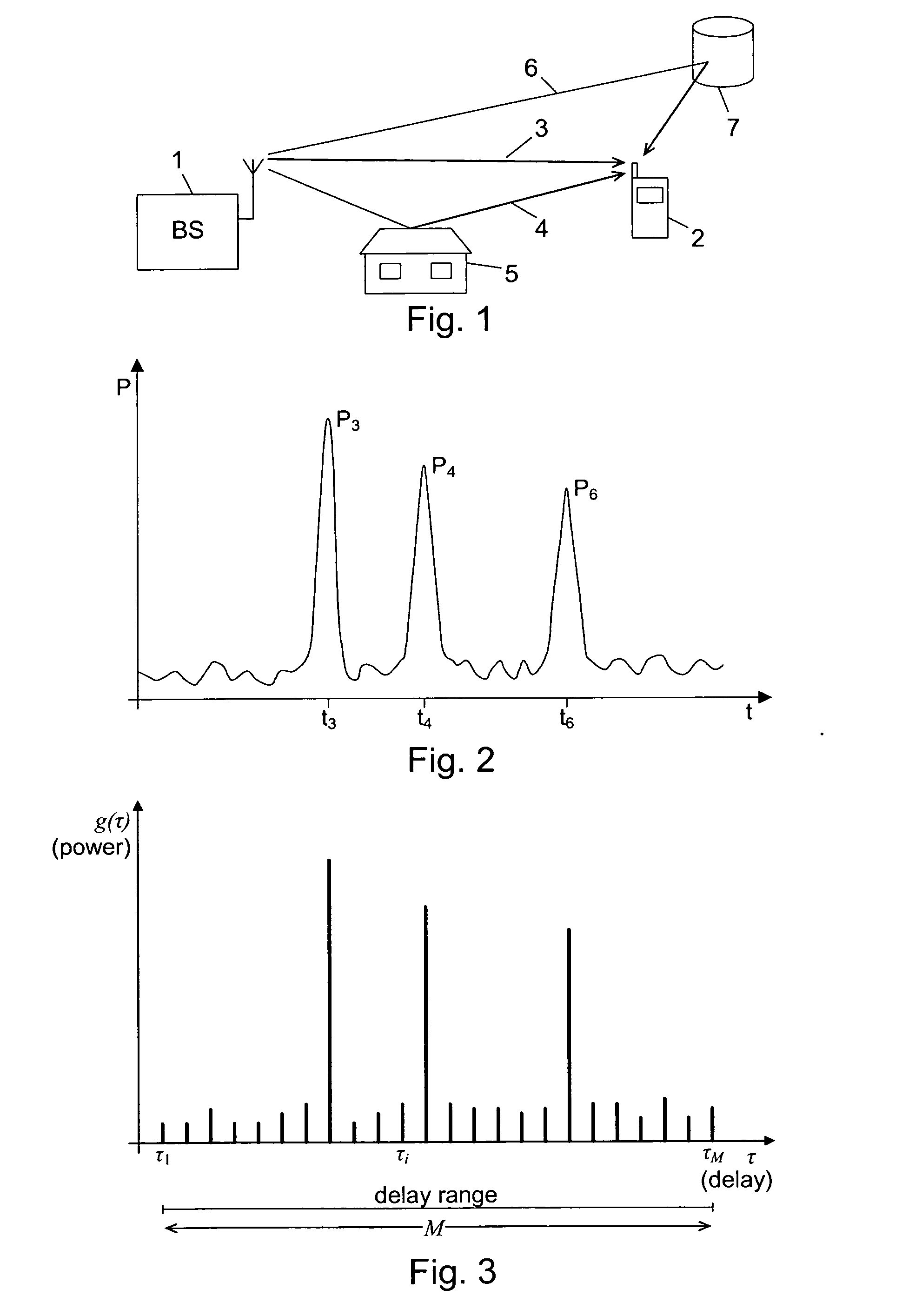
These different portions of the signal are a cause of interference in the receiver.
The effect of the combining depends on the instantaneous relationship of the carrier wavelength and distance differences, and it may thus for a given multipath component be either enhancing or destructive.
In case of destructive interference, the combining leads to significant decrease of the magnitude, or fading, of the path gain for that path.
Thus the gain of a true path may temporarily decrease considerably due to fading.
Furthermore, the timing of the demodulation must be synchronized, i.e. the despreading code must be applied to the received signal at the correct instant in time, which can be difficult due to the multipath effects mentioned above.
If the detected delays of the multipaths are off the correct values, the transmitted power carried by the paths are at least partly lost and the noise levels will be increased so that the performance of the receiver will be degraded.
Thus this two stage solution with the considerable number of despreaders has a correspondingly high current consumption, and a large dye area is occupied by the despreaders.
This is a disadvantage, because there is a continuing need to reduce the current consumption as well as the dye area of mobile terminals.
As an alternative to the two stage solution a wide search of high resolution could of course be conducted frequently to find the delays, but this solution would require an even larger dye area and have an even higher current consumption, and thus this is not a practical way of solving the problem.

Method used


Image

  • Selecting Delay Values for a RAKE Receiver
  • Selecting Delay Values for a RAKE Receiver
  • Selecting Delay Values for a RAKE Receiver

Examples


case i

[0144] The Nselected largest power values are from cell one, call this set S1. If a path from cell two is 100αcell% of the maximum power value for cell one, the weakest path is removed from the set S1 and it is replaced with the strongest path from cell two. This is done because we know that cell two is completely uncorrelated with the paths from cell one, and its contribution is therefore valuable.

case ii

[0145] The Nselected largest power values come from cells one and two, call this set S12. If a path from cell three is 100αcell% of the maximum power value for cell one, the weakest path is removed from the set S12, and it is replaced with the strongest path from cell three. If removing the weakest path means that cell two is not any more contained in the set S12, we remove instead the weakest path from cell one. For example, if Nselected equals six, and cell one contributes with the five strongest paths, we remove the weakest path from cell one and replace it with the strongest path from cell three. All other cells are ignored.

[0146]The procedure can readily be generalized to more cells. Above at most one delay has been replaced with a weaker delay from another cell, but this could also be generalized to comprise the replacement of several delays from multiple cells, however, at most one delay per newly introduced cell.

[0147]It should be observed, that except from the DPCH (Dedicat...


PUM


Abstract

Multipath components of transmitted data symbols are received with individual delays and processed by a RAKE having a number of fingers. A delay profile indicating magnitudes for a first number of delay values is provided. Estimated magnitudes for a second number of delay values located between the first number of delay values are calculated by interpolation, and a combined delay profile is provided by combining the magnitudes for the first and second number of delay values. Delay values for peaks in the combined delay profile are determined, and a number of peak delay values (P1, P2, P) comprising the largest peak are selected from the combined delay profile. At least some of the selected peak delay values are provided to the RAKE and assigned to the fingers. This allows a reduction of current consumption and dye area, while still providing delay values with sufficient resolution for the RAKE.

Description

TECHNICAL FIELD OF THE INVENTION[0001]The invention relates to a method of receiving digital data symbols from at least two transmitters through a transmission channel of a communications network, in which individual multipath components of a transmitted data symbol are received with individual delays, and wherein received signals are processed by a RAKE unit having a number of fingers, the method comprising the step of providing a delay profile for each transmitter from a set of received pilot signals; said delay profile being generated from the results of at least one path search and indicating a magnitude of received signal level for each of a first number of delay values. The invention further relates to a receiver for coded digital data symbols, and to a corresponding computer program and computer readable medium.DESCRIPTION OF RELATED ART[0002]In wireless communications systems the physical channel between a transmitter and a receiver is typically formed by a radio link. As an...

Claims


Application Information

Patent Timeline
Patent Type & Authority Applications(United States)
IPC IPC(8): H04L27/06H04B1/707
CPCH04B1/7113H04B1/7117H04B2201/709727H04B2201/70707H04B2201/70702
Inventor JONSSON, ELIASMYREHED, MARTEN
Owner TELEFON AB LM ERICSSON (PUBL)
Why Eureka
Try Eureka