Fuel Element for Pressurised Water Nuclear Reactors and Method of Loading Fuel Elements Into a Nuclear Reactor Core

Inactive Publication Date: 2009-02-12
ENUSA IND AVANZADAS
View PDF2 Cites 12 Cited by
  • Summary
  • Abstract
  • Description
  • Claims
  • Application Information

AI Technical Summary

Benefits of technology

[0029]This incorporation of medium-concentration gadolinium oxide provides a number of important advantages:
[0049]To avoid neutron shielding of the intra-nuclear detector which in some designs is introduced through the central instrumentation tube, preferably no rods with gadolinium oxide will be placed in the positions adjacent to the instrumentation tube.

Problems solved by technology

For longer cycles the excess reactivity at BOC is greater, and excessively high boron concentrations would be needed to compensate this, not admissible due to their adverse effect on the fuel and on the operation of the station.
With the introduction of low-leak schemes the power distribution tends to be less even, causing the appearance of local peaks that cannot be controlled only by adding an evenly distributed poison among the fuel assemblies, as is the case with boron dissolved in the coolant.
As a counterpart, the element resulting from neutron absorption is not completely inert, giving rise to a small remnant penalty during the entire lifetime of the fuel.
However, the applicant has conducted studies that show that the combination of these two types of fuel pellets / concentrations does not give optimum results.
In fact, the combination of only these two types of combustible poison pellets can even be insufficient for longer cycles, such as of 24 months, and / or in the case of possible increases in the rated power of the nuclear stations.
Aside from the fact that EP-A-1521271 does not specify how the gadolinium oxide content is distributed in the rods (for example, whether the percentage of gadolinium oxide of a rod is obtained by mixing pellets with a high concentration of gadolinium oxide with others having a low concentration of gadolinium oxide, to obtain a given average concentration), it is considered that many of the configurations described in EP-A-1521271 would not be technologically viable, and even if they were, including those indicated as preferred, many would not lead to the advantages described.

Method used


Image

  • Fuel Element for Pressurised Water Nuclear Reactors and Method of Loading Fuel Elements Into a Nuclear Reactor Core
  • Fuel Element for Pressurised Water Nuclear Reactors and Method of Loading Fuel Elements Into a Nuclear Reactor Core
  • Fuel Element for Pressurised Water Nuclear Reactors and Method of Loading Fuel Elements Into a Nuclear Reactor Core

Examples


examples and preferred embodiment

OF THE INVENTION

[0058]A fuel assembly design is presented below in accordance with a possible embodiment of the invention, comparing its results with those for an equivalent current design, including a comparison of the Li concentrations in the primary (in the coolant) corresponding to each design.

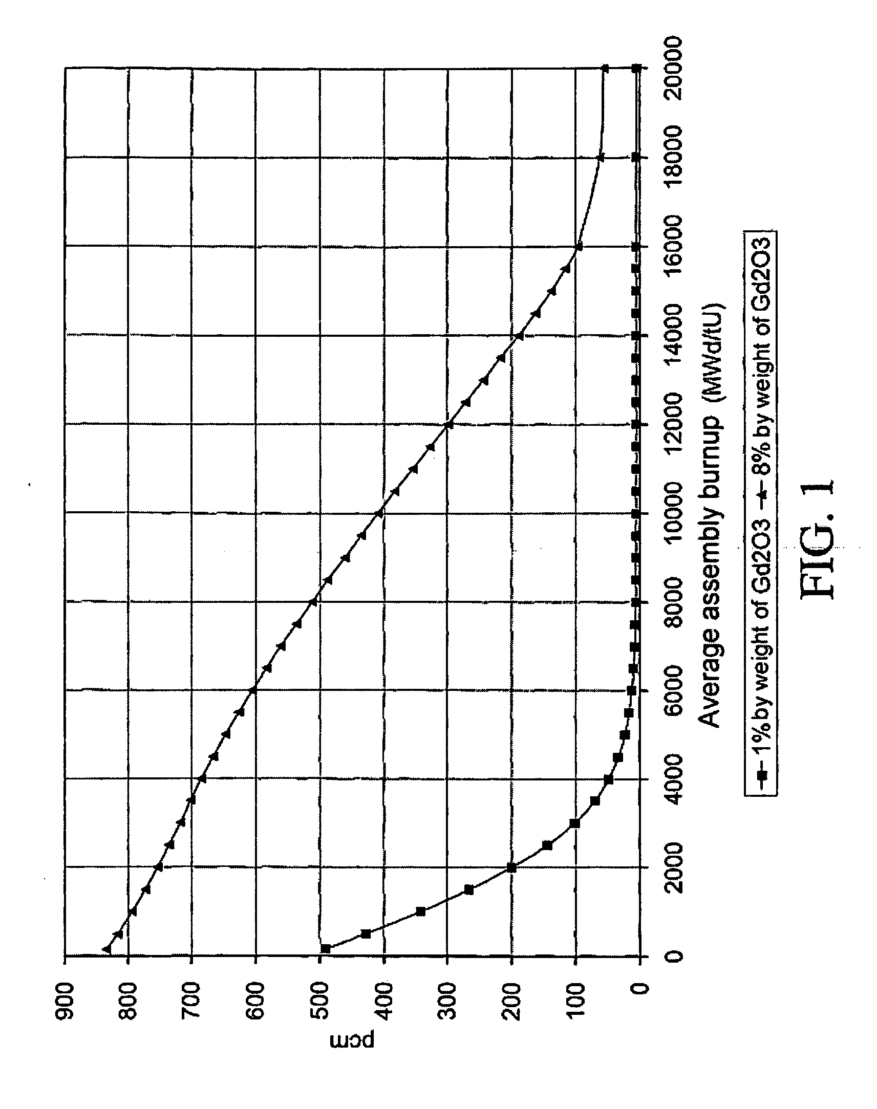
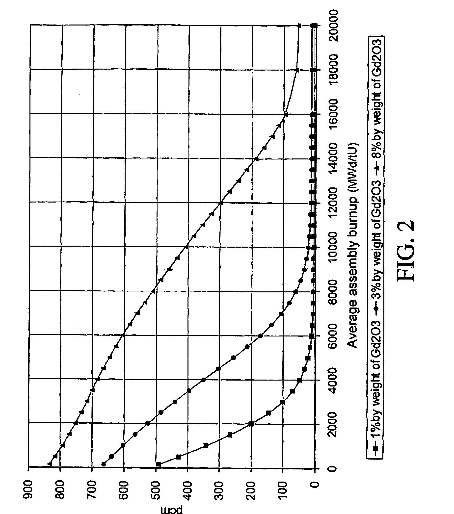
[0059]Firstly, FIG. 2 (vertical axis: effect on fuel assembly reactivity (pcm) for gadolinium oxide rod; horizontal axis: average assembly burnup in MWd / tU), based on FIG. 1, also shows the evolution on the effect on fuel assembly reactivity of a rod comprising pellets with a gadolinium oxide concentration of 3% by weight, allowing to compare this evolution with that of cases with pellets of concentrations 1% and 8%. As can be seen, gadolinium oxide at 3% concentration shows an intermediate evolution with burnup between that for low and high concentrations currently used in fuel assemblies, and it is understood to be best suited for use in long cycles, in which low-concentration gadolinium...


PUM


Abstract

The invention relates to a fuel assembly for pressurised water nuclear reactors comprising a plurality of nuclear fuel rods each of which comprises a plurality of pellets with nuclear fuel. The assembly includes both pellets with high-concentration gadolinium oxide (greater or equal to 6% by weight) and pellets with medium-concentration gadolinium oxide (greater than 2% by weight and less than or equal to 4% by weight).The invention also relates to a method for loading the core of a nuclear reactor.

Description

TECHNICAL FIELD OF THE INVENTION[0001]The invention lies in the field of nuclear power, and more specifically in the field of fuel assemblies used in Pressurised Water Reactors (PWR).BACKGROUND OF THE INVENTION[0002]There are various types of nuclear reactors, such as Boiling Water Reactors (BWR), pressurised water reactors (PWR), etc. In the aforementioned two types of reactor, fuel assemblies are used comprising a plurality of nuclear fuel rods, arranged in a matrix form, in rows and columns. These rods include pellets of fuel, such as uranium (U), in the form of uranium oxide (UO2), normally enriched in U-235.[0003]An example of a fuel assembly of this type, and of fuel rods and the corresponding fuel pellets is described in European patent application no. EP-A-0369305. Other examples of fuel assemblies and rods for pressurised water or boiling water reactors are described in patents or patent applications U.S. Pat. No. 4,587,090, U.S. Pat. No. 4,649,020, U.S. Pat. No. 4,728,487,...

Claims


Application Information

Patent Timeline
IPC IPC(8): G21C3/00
CPCG21C3/326G21C3/328G21C7/04G21Y2002/201Y02E30/39G21Y2004/10G21Y2004/30G21Y2004/403Y02E30/38G21Y2002/304Y02E30/30
Inventor MILDRUM, CLAUDE MICHELSERRANO RODRIGUEZ, JOSE FRANCISCO
Owner ENUSA IND AVANZADAS
Why Eureka
Try Eureka