Combustion liner stop in a gas turbine

Active Publication Date: 2009-02-19
GENERAL ELECTRIC CO
View PDF8 Cites 30 Cited by
  • Summary
  • Abstract
  • Description
  • Claims
  • Application Information

AI Technical Summary

Benefits of technology

[0014]In one embodiment, a liner stop for retaining a liner within a sleeve of a combustion system, is disclosed and includes: a female component including a saddle, the female component adapted for coupling to one of the liner and the sleeve; a male component in

Problems solved by technology

Prior liner stops have had difficulty in aligning the combustion liner in the flow sleeve, especially during assembly of the combustion system.
As a result the stops are not allowed to self align as the liner is inserted into the flow sleeve.
A misalignment between the liner and flow sleeve often resulted in the liner stops being non-uniformly loaded.
This requires the liner to be adjusted after being installed into the flow sleeve, which is difficult and time consuming given the liner is held into place by the hula seal.
In addition, the potential for misalignment between the combustion liner and flow sleeve has resulted in a relatively-high number of defects in combustion systems.
Prior combustion liner stops suffered from excessive wear of their contacting surfaces.
During operation of the combustion system, the liner stops may develop a wear cycle of increasing surface wear, which allows for greater vibratory movements between the liner stops, and which in turn causes even more surface wear.
When liner stops wear through and fail, the wearing surfaces in the combustion chamber may shift away from the liner stops to other surfaces that are not intended to be in rubbing contact.
Similarly, uni

Method used


Image

  • Combustion liner stop in a gas turbine
  • Combustion liner stop in a gas turbine
  • Combustion liner stop in a gas turbine

Examples


Example

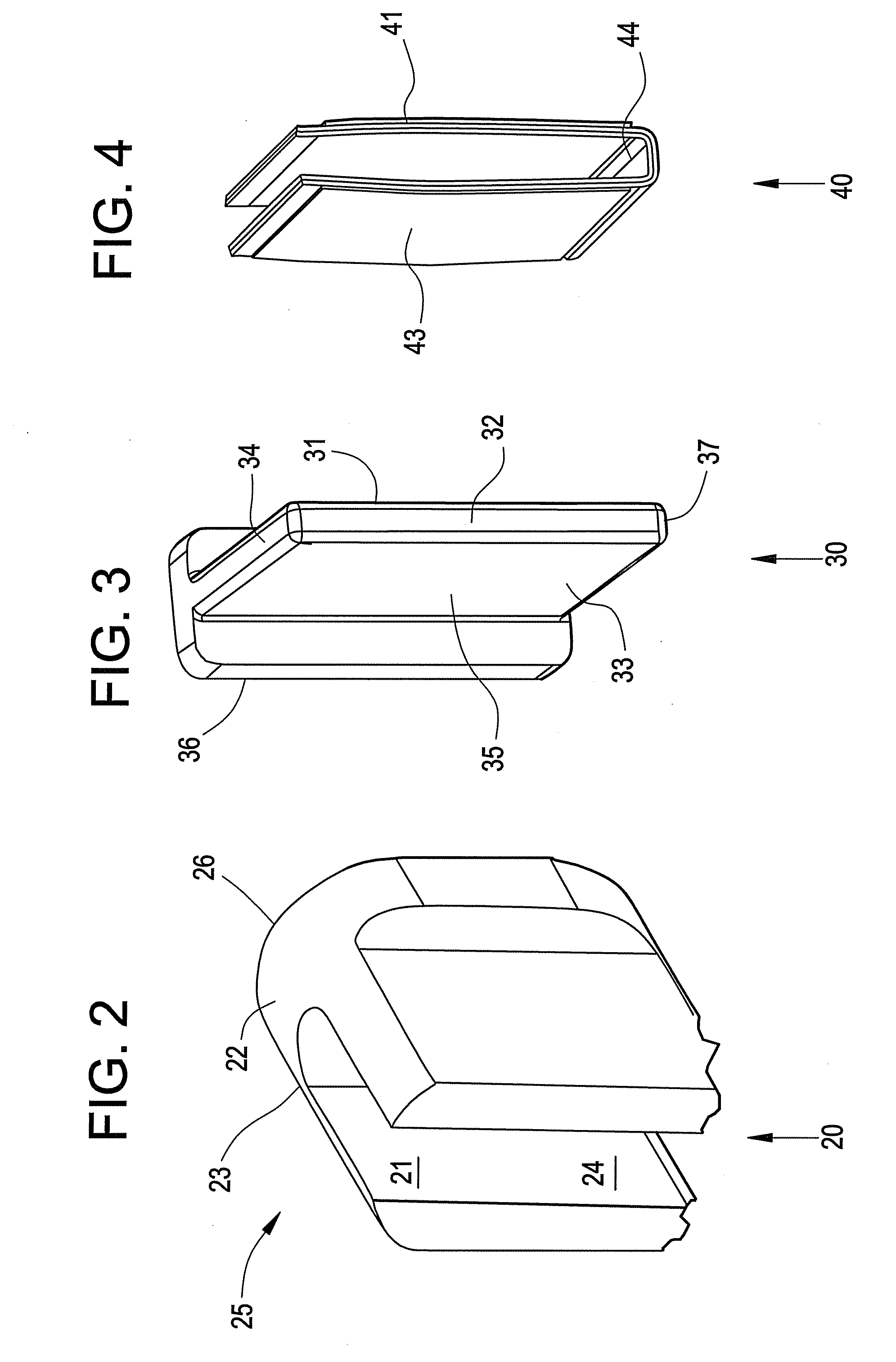
[0024]Disclosed is a liner stop that provides for at least one of installation and wear mitigation at the interfaces of a combustion liner and a flow sleeve within a combustion system, such as a gas turbine. The function may be provided by use of a plurality of liner stops which are generally disposed in an even distribution within the liner and the flow sleeve. The liner stop provides, as a result of the addition of an insert for increased damping of vibrations caused by rotor and combustion dynamics and increased ease of installation.

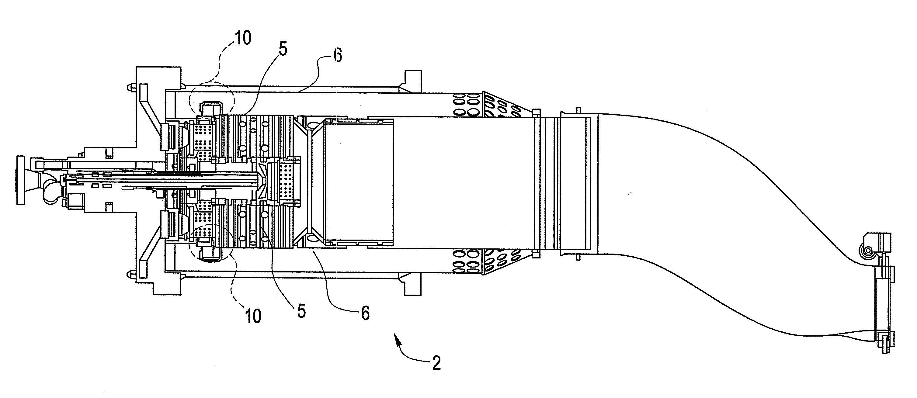
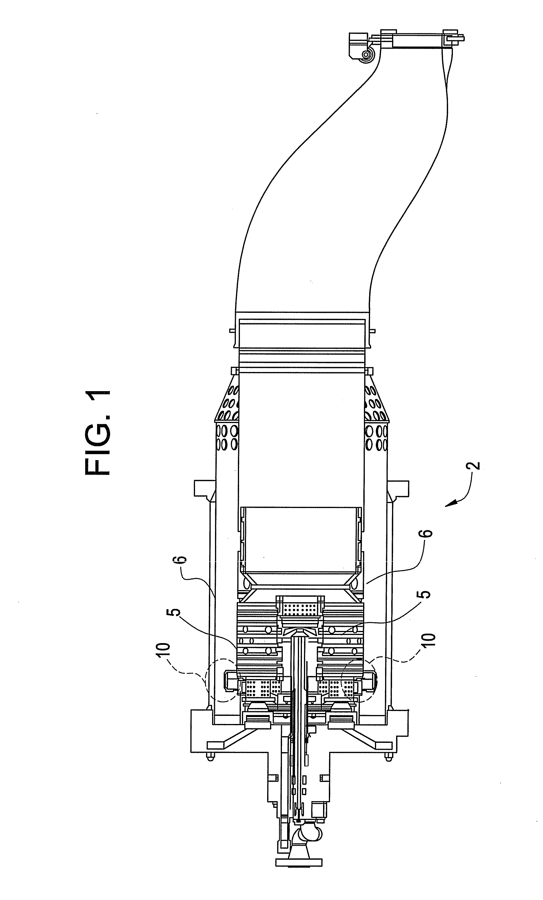
[0025]Referring now to FIG. 1, there is shown a cross section of aspects of a combustion system 2. The combustion system 2 generally includes a liner 5 and a flow sleeve 6. The liner 5 and the flow sleeve 6 are positioned relative to each other during assembly by use of a plurality of liner stops 10. In some embodiments, the combustion system 2 is generally cylindrical, and includes three liner stops 10, each liner stop 10 being about 120 degrees from...


PUM


Abstract

A liner stop for retaining a liner within a sleeve of a combustion system, includes: a female component including a saddle, the female component adapted for coupling to one of the liner and the sleeve; a male component including a tab for insertion into the saddle, the male component adapted for coupling to an opposite one of the liner and the sleeve; and an insert adapted for being attached to the tab and ensuring dampening of vibration when the tab is disposed within the saddle. A method and a system are also disclosed.

Description

BACKGROUND OF INVENTION[0001]1. Field of the Invention[0002]The present invention relates to combustion chambers in gas turbine engines, and in particular, the invention relates to mounting and alignment of combustion liners within the combustion chambers of gas turbines.[0003]2. Description of the Related Art[0004]The combustion system of a gas turbine generates hot gases to drive a turbine. The turbine, in turn, drives a compressor that provides compressed air for combustion in the combustion system. In addition, the turbine produces usable output power. A combustion system for a gas turbine may be configured as a circular array of combustion chambers arranged to receive compressed air from the compressor, inject fuel into the compressed air to create a combustion reaction, and generate hot combustion gases for the turbine. Each cylindrical combustion chamber includes one or more fuel nozzles, a combustion zone within the combustion liner, a flow sleeve surrounding and radially sp...

Claims


Application Information

Patent Timeline
IPC IPC(8): F02C3/14B21D39/03
CPCF02C7/20Y10T29/49885Y10T29/49826F23R3/60
Inventor PANGLE, ANSLEY MICHELLELEBEGUE, JEFFREY SCOTTPAQUIN, TODD DANIEL
Owner GENERAL ELECTRIC CO
Why Eureka
Try Eureka