

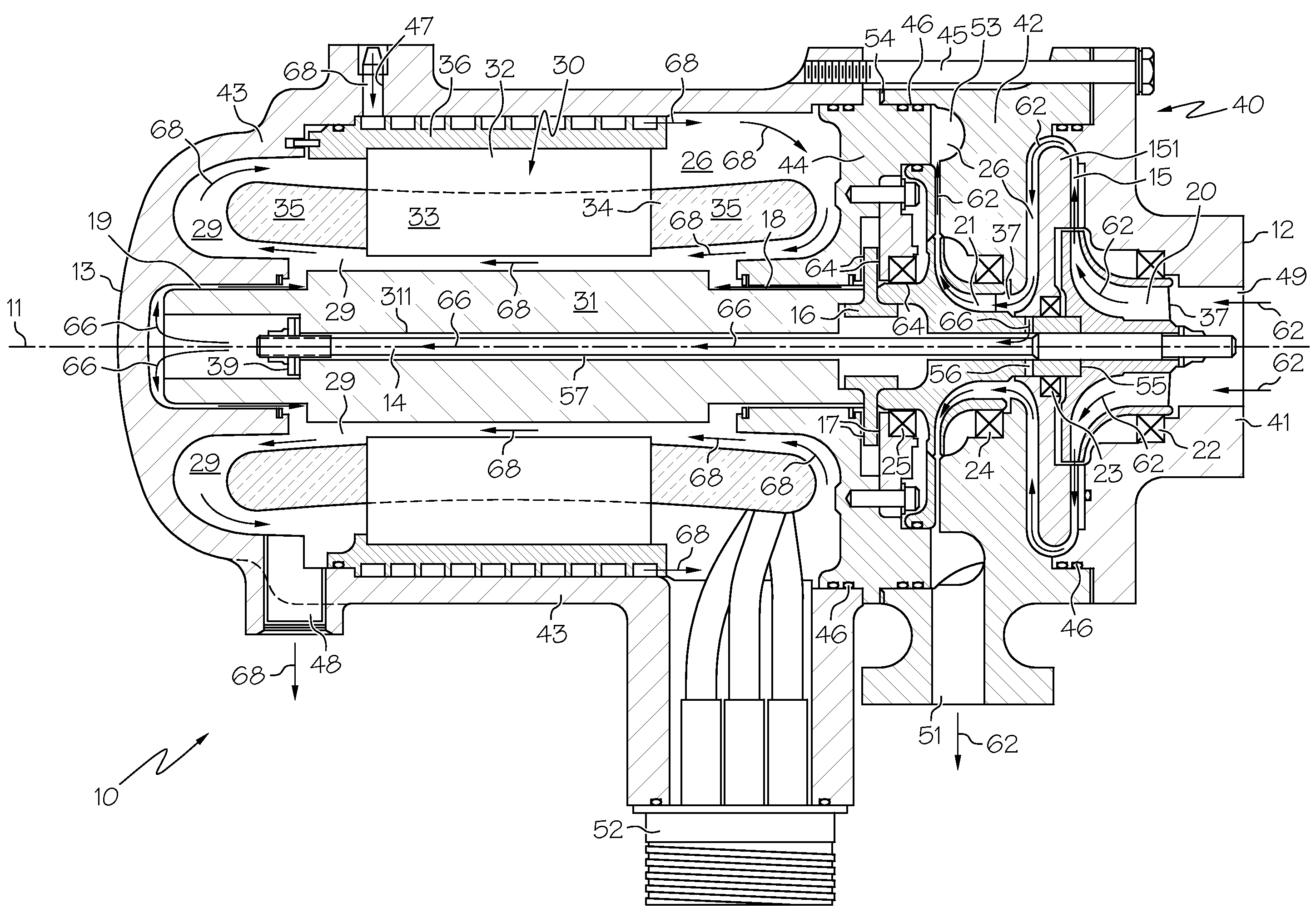
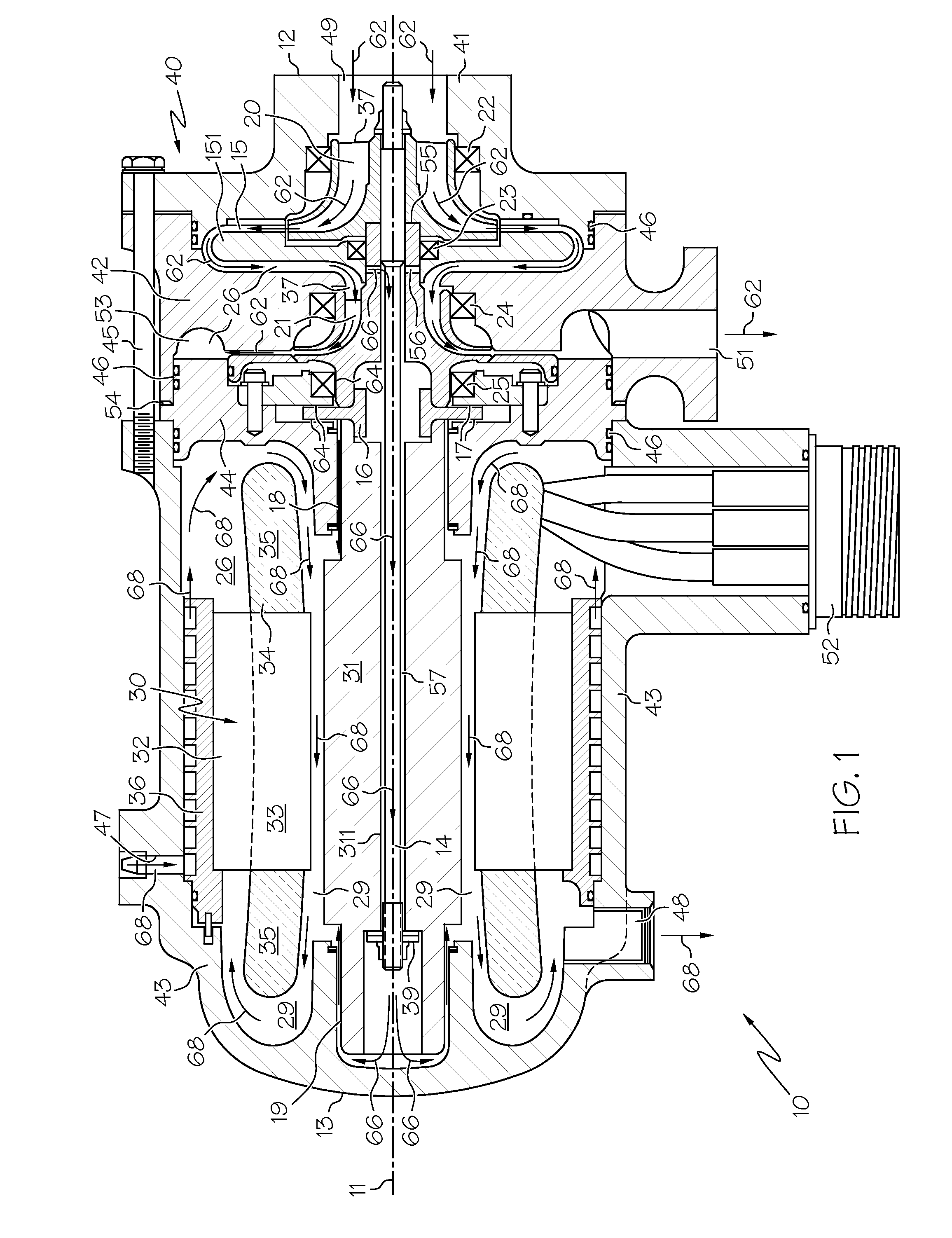
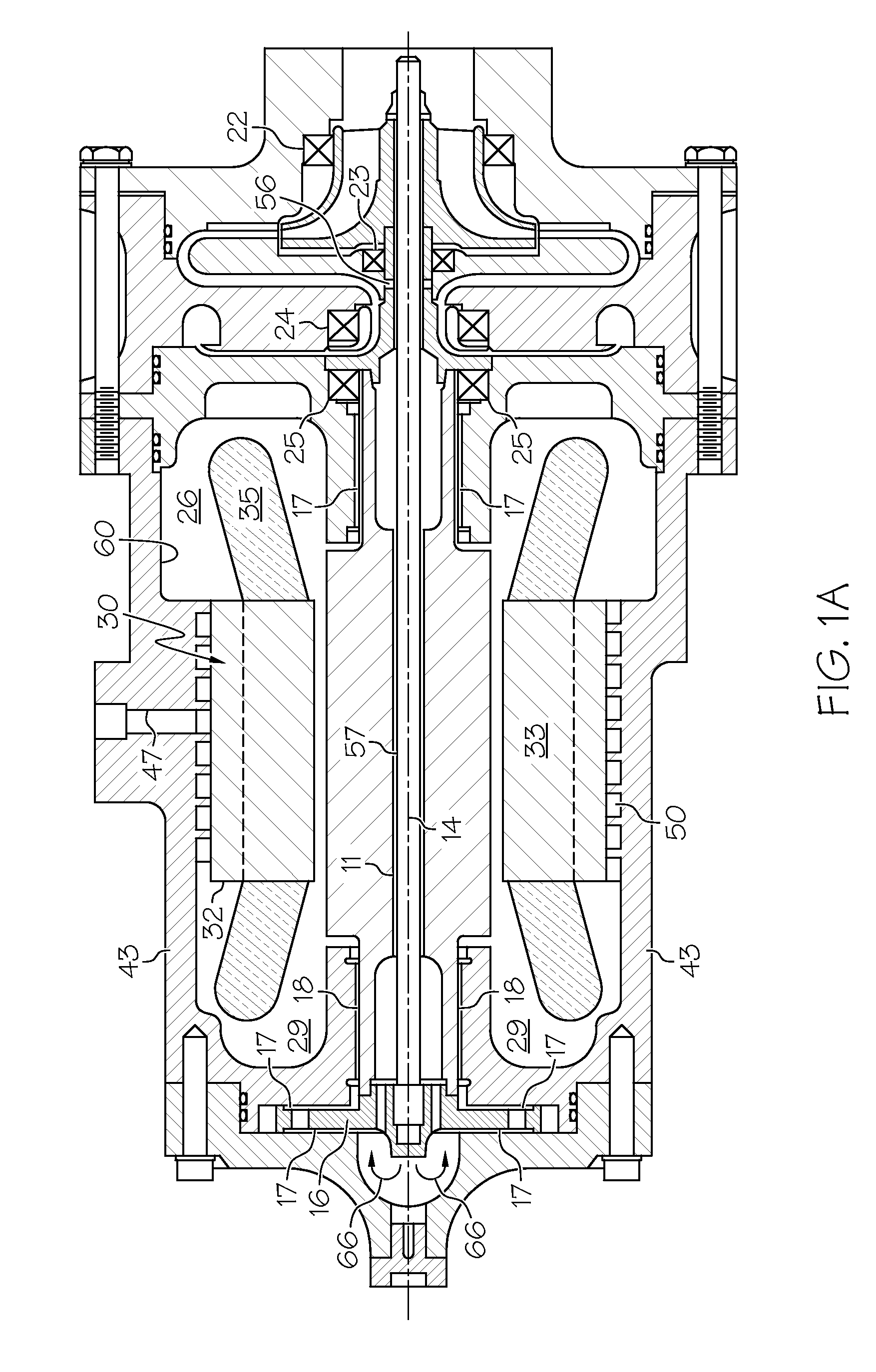
Two-stage vapor cycle compressor
a vapor cycle compressor and two-stage technology, applied in the direction of positive displacement liquid engines, pumping, lighting and heating apparatus, etc., can solve the problems of increasing the number of parts used in the compressor assembly, the layout may not allow a compact compressor design,
- Summary
- Abstract
- Description
- Claims
- Application Information
AI Technical Summary
Problems solved by technology
Method used
Image

Examples
Embodiment Construction
[0019]The following detailed description is of the best currently contemplated modes of carrying out the invention. The description is not to be taken in a limiting sense, but is made merely for the purpose of illustrating the general principles of the invention, since the scope of the invention is best defined by the appended claims.
[0020]Broadly, the present invention may provide a two-stage vapor cycle compressor and a method for vapor cooling an electrically driven two-stage vapor cycle compressor. In one embodiment, the present invention may provide a two-stage vapor cycle compressor that may be a relatively small and lightweight machine. The two-stage vapor cycle compressor according to one embodiment of the present invention may be gravity insensitive, and may withstand the environmental conditions of aerospace applications. In another embodiment, the present invention may provide a two-stage cycle compressor that has a simple layout, that may be relatively easy to assemble, ...
PUM
 Abstract
Description
Claims
Application Information