This helps you quickly interpret patents by identifying the three key elements:
Problems solved by technology
Method used
Benefits of technology
Benefits of technology
[0009]An object of the present invention is to provide a desiccant dehumidifier capable of lowering a temperature of suction air by installing a bypass line for bypassing a desiccant rotor, and of improving the quality of the internal air by mixing the internal air with the external air for dehumidifying.
Problems solved by technology
In addition, it is difficult to lower a temperature of suction air supplied into the interior.
Method used
Image
Click on the blue label to locate the original text in one second.
Reading with bidirectional positioning of images and text.
Examples
first embodiment
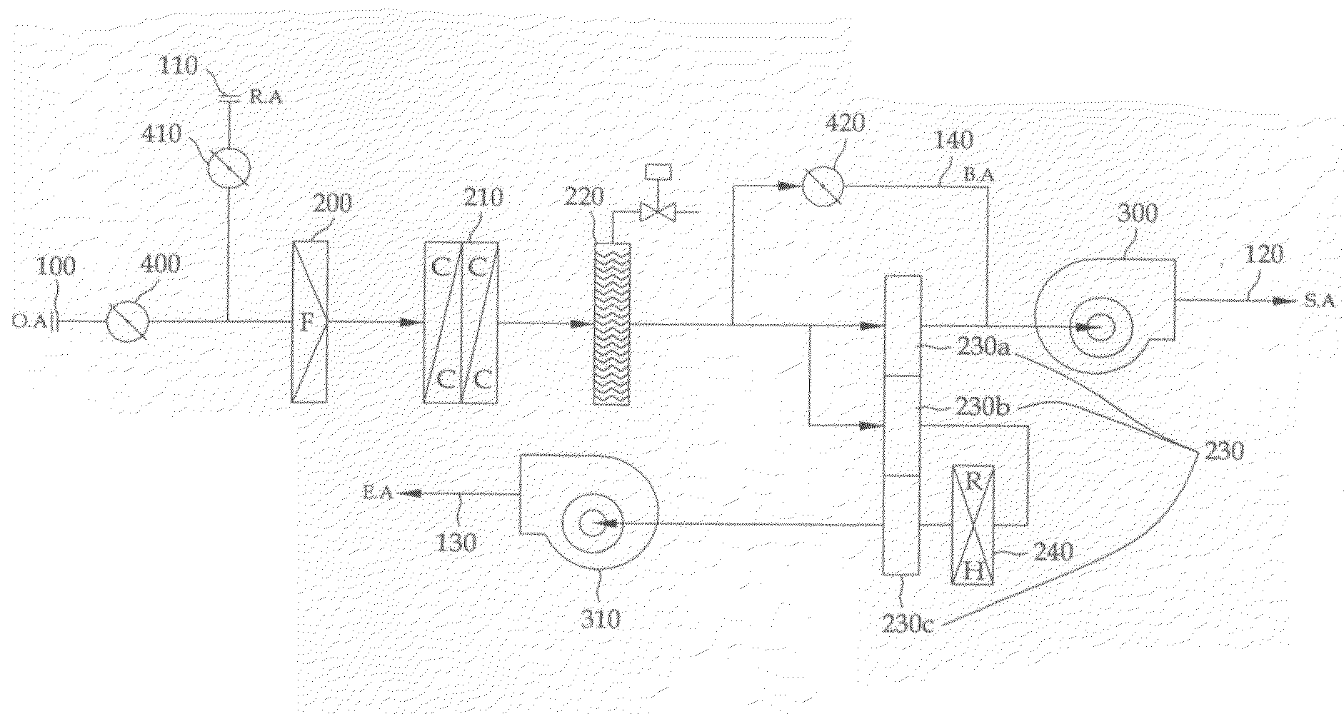
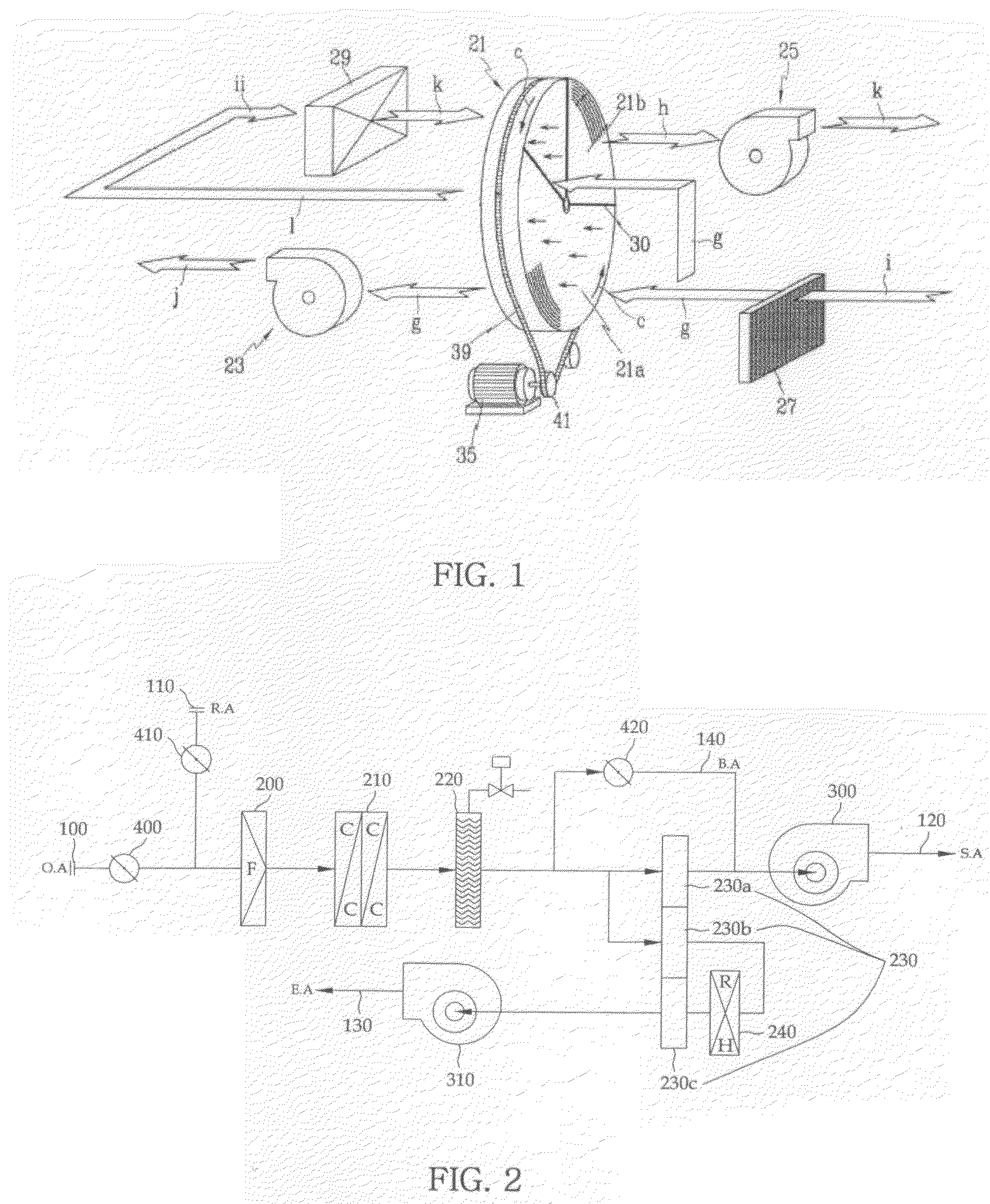
[0030]As shown in FIG. 2, a desiccant dehumidifier in accordance with a first exemplary embodiment of the present invention includes an external air damper 400 for introducing external air 100 and controlling an amount of the external air, a ventilation damper 410 introducing ventilation air 110 entering from the interior and controlling an amount of the ventilation air, an air filter 200, a cooling coil 210, an eliminator 220, a desiccant rotor 230 accommodating a dehumidifying section 230a, a purge section 230b and a recycling section 230c, a suction fan 300, and an exhaust fan 310.
[0031]Specifically, the external air 100 introduced from the exterior into the desiccant dehumidifier may be introduced, blocked or quantitatively adjusted through the external air damper 400, and the ventilation air 110 introduced from the interior may be introduced, blocked or quantitatively adjusted through the ventilation damper 410.
[0032]The external air 100 and the ventilation air 110 introduced a...
second embodiment
[0055]Hereinafter, another embodiment in accordance with the present invention will be described with reference to FIG. 6.
[0056]A desiccant dehumidifier in accordance with a second exemplary embodiment of the present invention uses two cooling coils 210 to increase dehumidifying efficiency of external air 100, dissimilar to the first embodiment.
[0057]In this case, the external air 100 is introduced to pass through a first air filter 200 and then is cooled by a first cooling coil 210a, and ventilation air 110 passes through a second air filter 200′ and then is mixed with the external air 100 passed through the first cooling coil 210a to pass through a second cooling coil 210b.
[0058]In addition, as shown in FIG. 7, similar to the case of FIG. 4 described to perform heating when an external temperature is very low, a bypass heater 250 is installed at a bypass line, and a suction air heater 260 may be installed at a discharge port of a suction fan 300 depending on necessity.
third embodiment
[0059]Hereinafter, another embodiment in accordance with an exemplary embodiment of the present invention will be described with reference to FIG. 8.
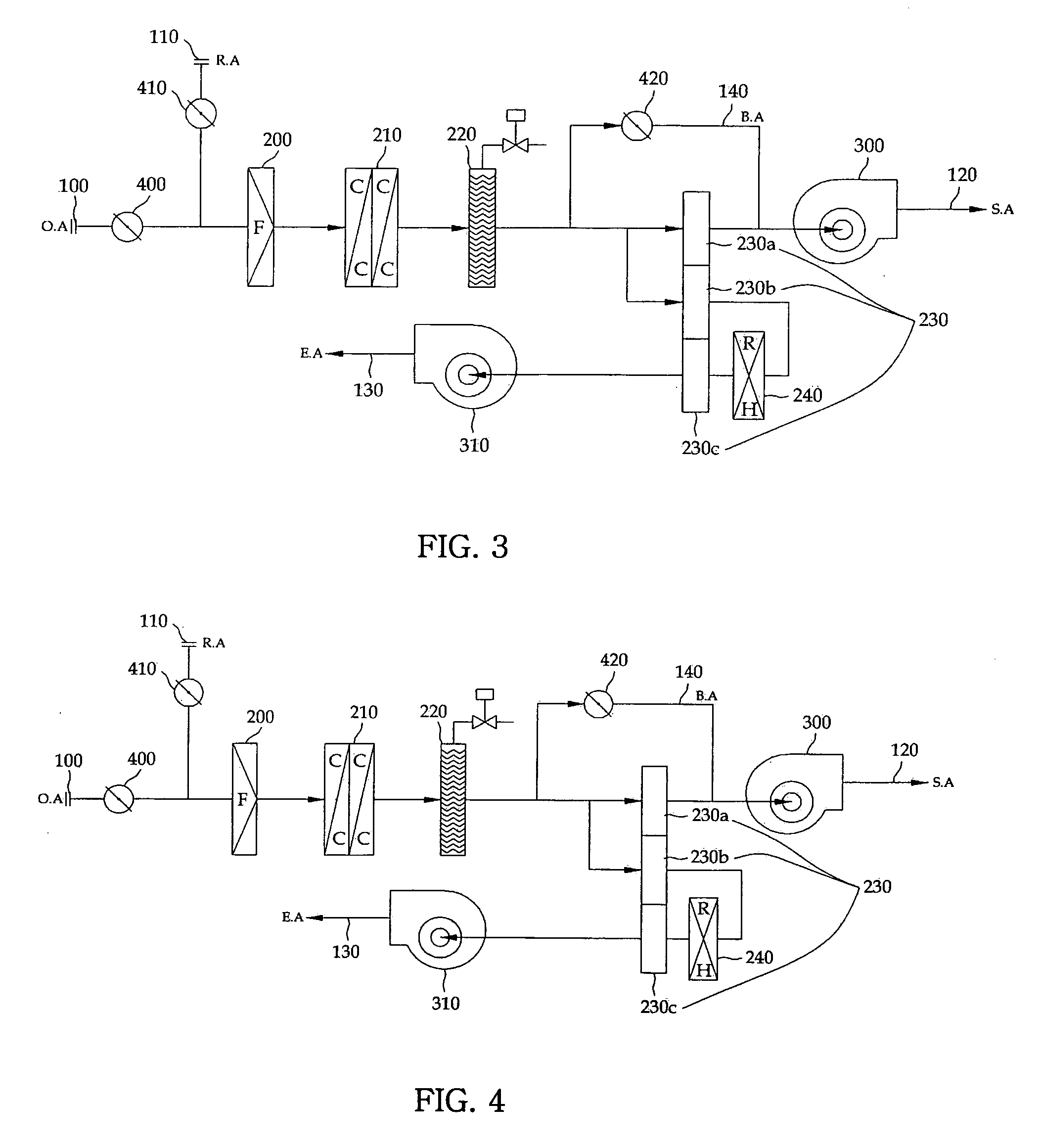
[0060]A desiccant dehumidifier in accordance with a third exemplary embodiment of the present invention is provided to be readily used when external humidity is high. Dissimilar to the second embodiment, ventilation air 110 is separated from external air 100 such that the external air 100 and the ventilation air 110 pass through separate air filters 200 and 200′ and cooling coils 210a and 210b, are separately cooled, and are then mixed with each other.
[0061]That is, when the ventilation air 110 has humidity significantly different from the external air 100, since a humidifying load is increased when the external air 100 is not cooled separately from the ventilation air 110, the external air 100 and the ventilation air 110 are cooled and then mixed with each other to pass through the desiccant rotor 230 disposed at the dehumidifying sect...
PUM
Abstract
Provided is a desiccant dehumidifier characterized in that: external air is introduced through a cooling coil and an eliminator; the introduced external air is bifurcated into a desiccant rotor and a bypass line in front of the desiccant rotor; the external air bifurcated to the desiccant rotor passes through the desiccant rotor disposed at a dehumidifying section to perform dehumidification, and the bypass air passed through the bypass line is mixed with the air passed through the desiccant rotor behind the desiccant rotor to form suction air to be supplied through a suction fan; and a part of the external air bifurcated to the desiccant rotor passes through the desiccant rotor disposed at a purge section, and then passes through the desiccant rotor disposed at a recycling section via a recycling heater to form exhaust air to be exhausted through an exhaust fan, wherein ventilation air is introduced through a separate path on a path through which the external air is introduced and then mixed with the external air.Therefore, the bypass line is installed to bypass the desiccant rotor during an external air dehumidification process so that the bypass air passed through the bypass line is mixed with the suction air dehumidified through the desiccant rotor and the internal air is mixed with the external air to improve quality of the internal air.
Description
CROSS-REFERENCE TO RELATED APPLICATION[0001]This application claims the benefit of Korean Patent Application No. 10-2007-0081178, filed on Aug. 13, 2007, the disclosure of which is hereby incorporated herein by reference in its entirety.BACKGROUND OF THE INVENTION[0002]1. Field of the Invention[0003]The present invention relates to a desiccant dehumidifier, and more particularly, to a desiccant dehumidifier capable of lowering a temperature of supplied air using bypass air and of dehumidifying the interior mixing vent air in the interior with external air.[0004]2. Description of the Prior Art[0005]In general, a desiccant dehumidifier is an apparatus for sucking moist air to pass through a heat exchanger including a condenser and an evaporator through which a refrigerant flows, or a desiccant to lower humidity of the supplied air, and supplying the dehumidified air into the interior to lower humidity in the interior.[0006]An example of a conventional desiccant dehumidifier is disclos...
Claims
Application Information
Patent Timeline
Application Date:The date an application was filed.
Publication Date:The date a patent or application was officially published.
First Publication Date:The earliest publication date of a patent with the same application number.
Issue Date:Publication date of the patent grant document.
PCT Entry Date:The Entry date of PCT National Phase.
Estimated Expiry Date:The statutory expiry date of a patent right according to the Patent Law, and it is the longest term of protection that the patent right can achieve without the termination of the patent right due to other reasons(Term extension factor has been taken into account ).
Invalid Date:Actual expiry date is based on effective date or publication date of legal transaction data of invalid patent.

