Magnetically supported sliding track system

a sliding track and magnetic technology, applied in the direction of door/window protective devices, door/window fittings, constructions, etc., can solve the problems of not being supported, not well constrained, and subject to front to back movement, so as to prevent intruder entry, reduce sliding friction, and high friction level

Inactive Publication Date: 2009-02-19
SINGISER JOSEPH +1
View PDF19 Cites 28 Cited by
  • Summary
  • Abstract
  • Description
  • Claims
  • Application Information

AI Technical Summary

Benefits of technology

[0017]The present invention provides a sliding door or window that is supported by repulsion of magnets that are placed on the bottom surface of a slider and the opposing portion of the stationary track. Since the repulsion essentially reduces or in a preferable mode entirely eliminates the gravitational downward load of the sliding door or window on the bottom track, the movement of the sliding door or window is accomplished with very little or no frictional resistance. The front to back movement of the magnetically supported sliding door or window is prevented by use of a plurality of low friction polymeric knobs in the stationary doorframe that contact the front and back surface of the sliding door or window.
[0018]Generally, the invention of the magnetically supported sliding track system broadly comprises: (i) a stationary frame having frame sides, an upper portion, and a lower portion; (ii) said lower portion of said frame having a channel with a lower track, wherein said lower track further includes one or more magnets, which may be permanent magnets or electromagnets such that the magnetic polarity of the magnets points upwards; (iii) a sliding portion having sides, a top, and a base; (iv) said base of said sliding portion including one or more magnets, which may be permanent magnets or electromagnets such that the bottom surface of the base of the sliding portion has an identical magnetic polarity pointing downwards; and (v) said base magnet of sliding portion and said stationary track magnets have same magnetic polarity so that said base magnet and stationary track magnet repel one another causing a force which forms a cushion between said base magnet and said stationary track magnet. Wherein the sliding portion glides upon the cushion formed by the force between the base and the lower track, enabling easy friction-free movement between the sliding portion along the track of the frame.
[0019]The repulsing between the magnet at the base and at the bottom of the sliding door tends to displace the sliding door in every possible direction due to the cushioning effect of the magnetic fields. However, the sliding door is constrained in its movement within said channel of the stationary frame lower portion, which has two polymeric knobs preventing front to back displacement of the sliding door or window. In addition, two similar polymeric knobs present on the upper channel of the stationary frame constrain the sliding door from front to back displacement. As a result, the sliding door or window can only move along the sliding direction. The door weight is entirely supported by the cushioning force between the repelling magnets and the sliding door or window essentially appears to ‘float on air’ over the stationary frame lower track magnet. Advantageously, the sliding movement of the door or window occurs with little or no friction, since substantially all of the sliding friction is extant only at the polymeric knobs, which contact the sliding door. The coefficient of friction between a polymer such as high molecular weight polyethylene or polytrtrafluroethylene (PTFE) and a metal is generally very low, typically below 0.1. Moreover, the contact force between the polymeric knobs and the door is merely a small lateral force, since substantially the entire weight of the door is supported by the magnetic cushioning force. The frictional drag force is equal to the contact load times the coefficient of friction. The load in the vertical direction is small due to the support provided by the repulsive magnetic force and therefore, the frictional drag is very small. In the front to back direction, there is essentially no load and the low coefficient of friction of the polymeric knobs offer very little frictional drag. As a result, this configuration provides very smooth sliding movement of the sliding door or window.

Problems solved by technology

Since the magnets support only in the vertical direction, the sliding door is subject to front to back movement, which is not well constrained.
Magnetic attractive forces support the suspended load; but the load is not supported by magnetic repulsion at the bottom of the load.

Method used


Image

  • Magnetically supported sliding track system
  • Magnetically supported sliding track system
  • Magnetically supported sliding track system

Examples


Embodiment Construction

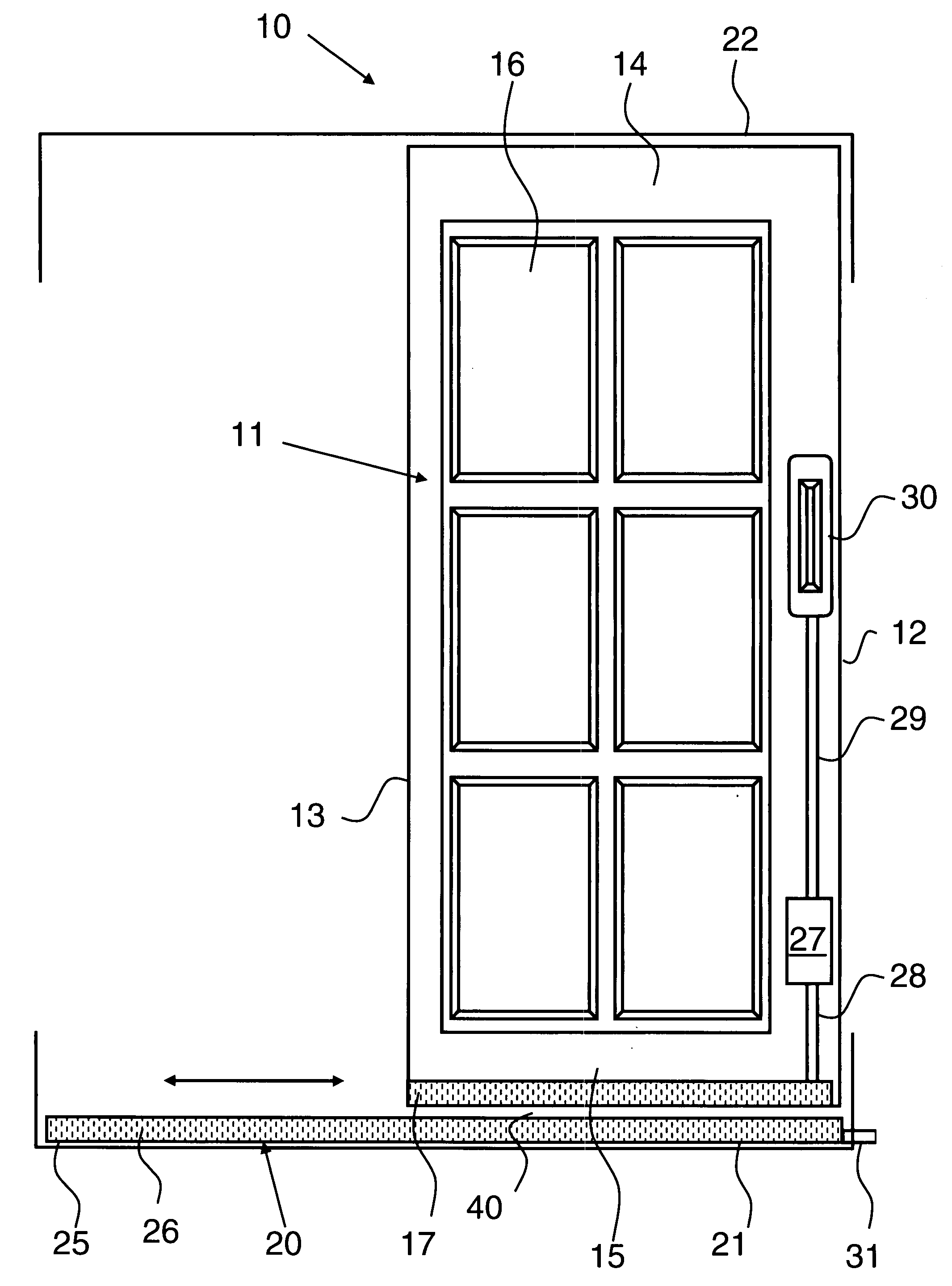
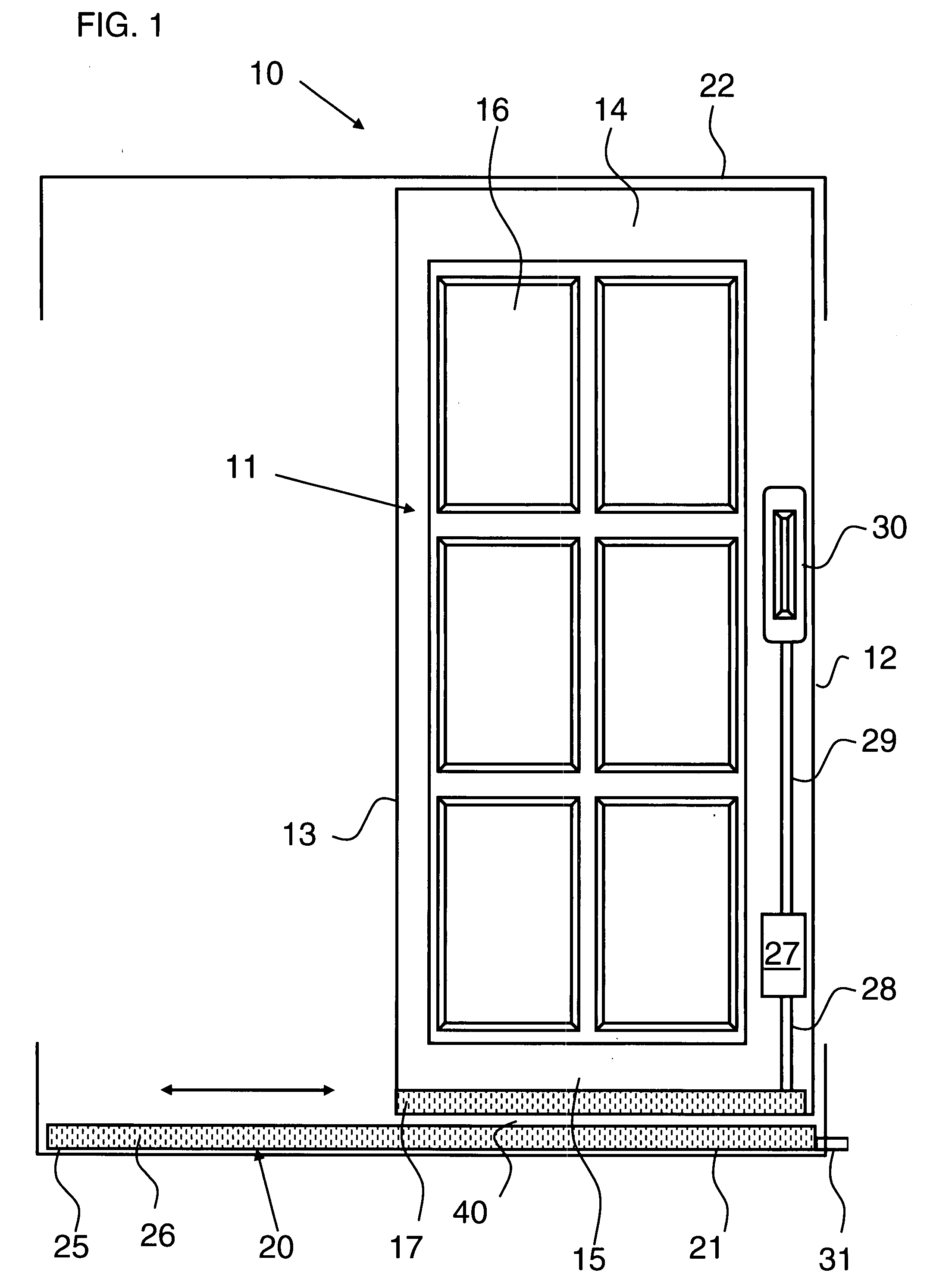
[0028]Assemblies for sliding doors and windows are currently constructed using a track and rail arrangement. The rail mates with a groove located within the bottom of a frame and the bottom of a sliding door / window, respectively, and / or visa versa. These currently utilized sliding track rail-groove assemblies require continuous maintenance as they are highly susceptible to corrosion from weather and blockage from dirt and debris. Corrosion and blockage causes damage to the track assembly, causing the mating rail and groove to become disengaged thereby making it difficult, if not impossible, to slide the door or window to the desired position. As a result, these sliding track assemblies and / or doors and windows typically need repair and / or replacement on a semi-regular basis. Regular repair and replacements increase the time and expense required to maintain these doors and windows.

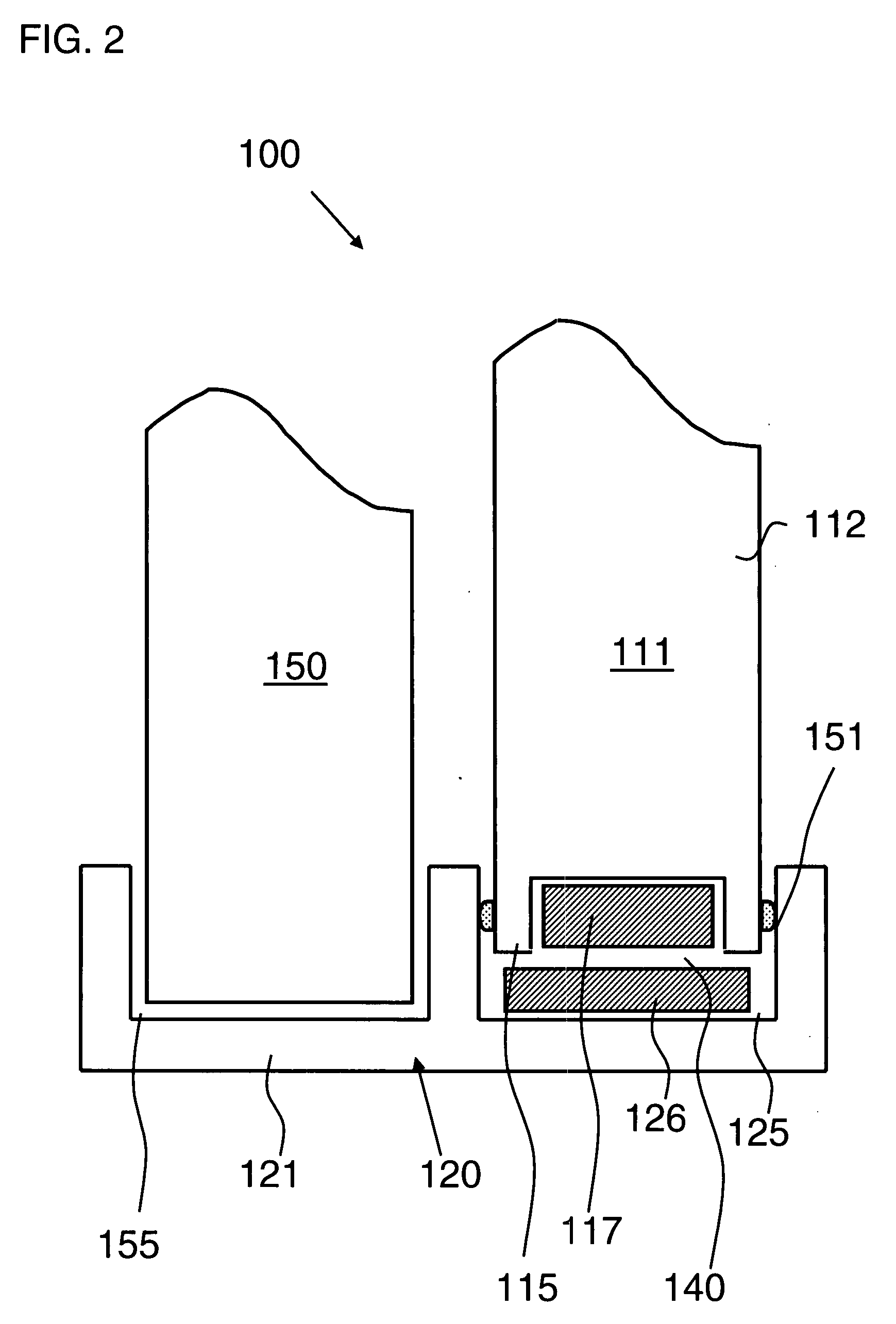
[0029]Generally the invention of the magnetically supported sliding track system broadly comprises: (i) ...


PUM


Abstract

A sliding door or window supporting system has a stationary frame with a bottom track and a sliding portion that slides from a closed position to an open position. The bottom portion of the sliding portion and the upper surface of stationary frame track are provided with one or more magnets having identical magnetic polarity, thereby creating repulsion between the bottom of the sliding portion and the stationary track. Forces produced by magnetic repulsion lift the weight of the sliding portion, creating an air gap. A smooth, low friction sliding and door gliding movement results, which is immune to dirt and debris. The front to back movement of the sliding portion is supported by low friction polymeric knobs attached to a stationary frame and contacting sliding portion.

Description

BACKGROUND OF THE INVENTION[0001]1. Field of the Invention[0002]The present invention relates to a magnetically supported sliding track suited for sliding doors and windows; and, more particularly to a sliding track for a door or window that provides minimal friction for sliding and may be optionally locked by electrical means from any sliding movement.[0003]2. Description of the Prior Art[0004]Many patents address issues related to a magnetically supported sliding window or door. The magnetic supports disclosed in the prior art hang the window or door in a magnetic support and use additional supporting means such as wheels or rods. In such cases, the easy-to-slide door or window is not supported by magnetic repulsion provided at the bottom track of the sliding door or window.[0005]U.S. Pat. No. 4,698,876 to Karita discloses a door apparatus partially supported by a magnetic mechanism. Magnets mounted on the upper surface of the sliding door attract a stationary guide member. Even t...

Claims


Application Information

Patent Timeline
Patent Type & Authority Applications(United States)
IPC IPC(8): E05D15/06E05D15/00
CPCE05D15/0682E05Y2900/132E05Y2900/148E05D2015/0695
Inventor SINGISER, JOSEPHLIEDMAN, ELI A.
Owner SINGISER JOSEPH
Why Eureka
Try Eureka