Ball seat having fluid activated ball support

a technology of fluid activation and ball support, which is applied in the field of ball seats, can solve the problems of plastic balls that have limited compressive strength and fail, and achieve the effects of reducing the likelihood of ball contact force, and reducing the stress on the ball

Active Publication Date: 2009-02-19
BAKER HUGHES INC
View PDF53 Cites 113 Cited by
  • Summary
  • Abstract
  • Description
  • Claims
  • Application Information

AI Technical Summary

Benefits of technology

[0012]By making contact with, or engaging, the ball, the plug element support members provide mechanical support for the ball. Accordingly, the existing seat contact area between the seat and the ball maintains pressure seal, but the resulting force against the ball caused by pressurization of the ball against the seat is spread out between the existing seat contact area and the additional contact area provided by the extended plug element support members. As the pressure is increased, the force on the ball is transferred to both the original seal area of the seat and to the plug element support members. The applied pressure to the plug element support members, therefore, decreases the likelihood that the force on the ball will push the plug element support members back in. Therefore, the resulting contact force is effectively reduced and, thus, the stresses on the ball are likewise reduced.
[0013]Due to the plug element support members providing additional support to the ball, the ball seats disclosed herein provide a plugging method where higher pressure can be exerted onto a seat by a lower strength ball without exceeding the ball's bearing or load strength. For example, the pressure ratings for certain seat configuration/ball strength designs may be increased two or more times greater than current low strength balls by inc

Problems solved by technology

The ball, however, is typically formed out of a plastic material that has limited compressive strength.
This

Method used


Image

  • Ball seat having fluid activated ball support
  • Ball seat having fluid activated ball support
  • Ball seat having fluid activated ball support

Examples


Embodiment Construction

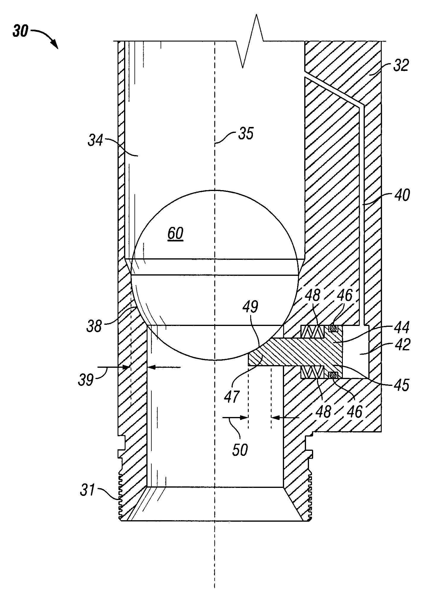
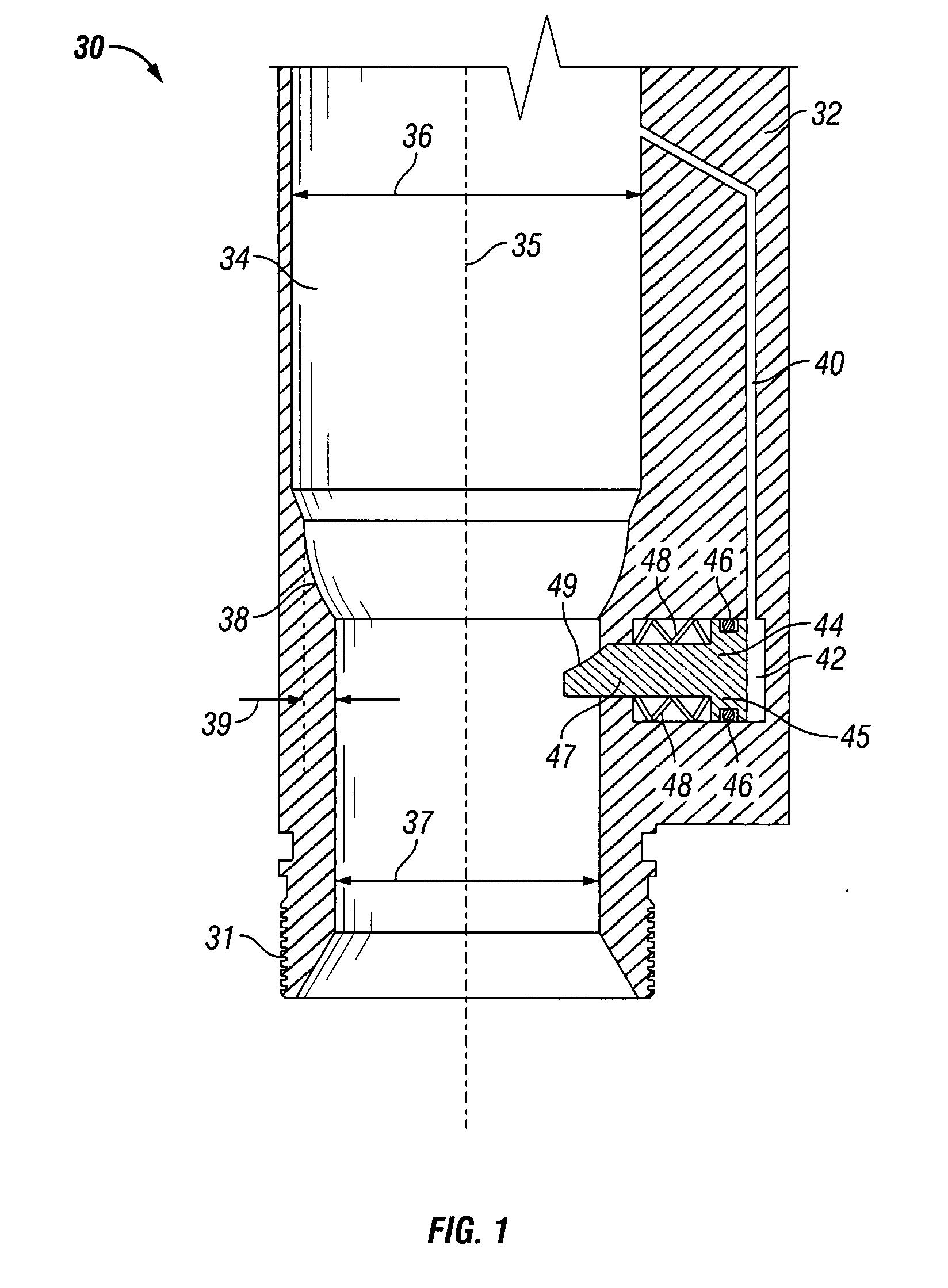
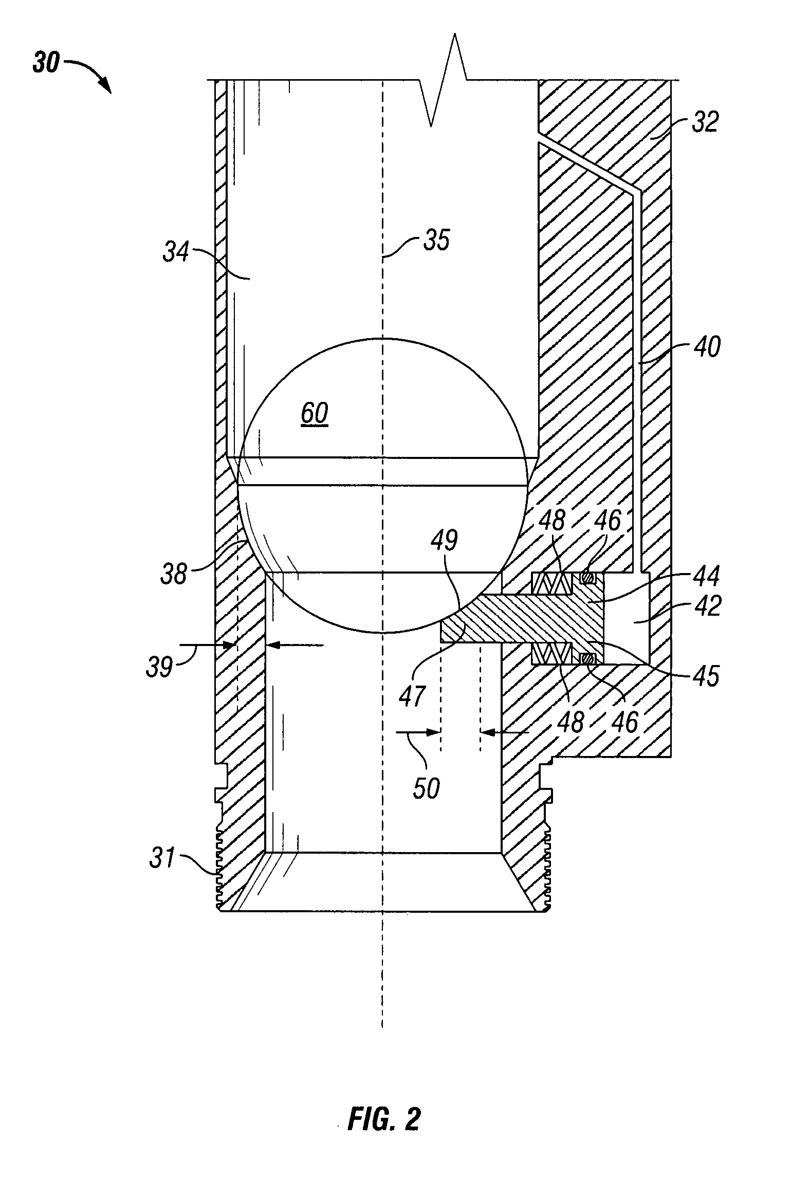
[0027]Referring now to FIGS. 1-2, ball seat 30 includes a sub or housing 32 having bore 34 defined by an inner wall surface and having axis 35. Bore 34 is divided by seat 38 into an upper portion defined by inner diameter 36 and a lower portion defined by inner diameter 37. Inner diameter 36 is also referred to as the “outer diameter of the contact area,” and inner diameter 37 is also referred to as the “seat inner diameter” or “inner diameter of the seat.” Seat 38 provides contact area 39. Therefore, the outer diameter of contact area 39 is defined by inner diameter 36 and the inner diameter of contact area 39 is defined by inner diameter 37. Attachment members such as threads 31 are disposed along the outer diameter of housing 32 for securing ball seat into a string of conduit, such as drill pipe or tubing. Additional attachment members (not shown) are also included at the opposite end (not shown) of ball seat 30.

[0028]Housing 32 includes passage or passageway 40 that fluidly conn...


PUM


Abstract

Apparatuses for closing a well conduit comprise a housing having a longitudinal bore and a seat disposed within the bore. A chamber is disposed within the housing and includes a plug element support member, such as ram or piston, operatively associated within the chamber. The plug element support member has a retracted position and an extended position. A passageway is in fluid communication with the bore and the chamber. A plug element such as a ball or drop plug, is adapted to be disposed into the bore and landed on the seat to restrict fluid flow through the bore and the well conduit. Landing the plug element causes and allowing fluid pressure to build causes the plug element support member to move from the retracted position to the extended position to provide support to the plug element landed on the seat.

Description

BACKGROUND[0001]1. Field of Invention[0002]The present invention is directed to ball seats for use in oil and gas wells and, in particular, to ball seats having one or more fluid activated ball support.[0003]2. Description of Art[0004]Ball seats are generally known in the art. For example, typical ball seats have a bore or passageway that is restricted by a seat. The ball or drop plug is disposed on the seat, preventing fluid from flowing through the bore of the ball seat and, thus, isolating the tubing or conduit section in which the ball seat is disposed. As the fluid pressure above the ball or drop plug builds up, the conduit can be pressurized for tubing testing or actuating a tool connected to the ball seat such as setting a packer. Ball seats are also used in cased hole completions, liner hangers, flow diverters, frac systems, and flow control equipment and systems.[0005]Although the terms “ball seat” and “ball” are used herein, it is to be understood that a drop plug or other...

Claims


Application Information

Patent Timeline
IPC IPC(8): E21B34/08E21B34/06
CPCE21B34/14Y10T137/7867Y10T137/7866E21B34/142
Inventor SCHASTEEN, THOMASKING, JAMES G.
Owner BAKER HUGHES INC
Why Eureka
Try Eureka