Clutch Damper Spring Pocket Improvement

a damper spring and damper technology, applied in the field of friction clutches, can solve the problems of gear rattle, premature wear of driveline components, audible noise, and vibration not only emitted by torsional vibration,

Active Publication Date: 2009-02-19
EATON INTELLIGENT POWER LIMITED
View PDF6 Cites 22 Cited by
  • Summary
  • Abstract
  • Description
  • Claims
  • Application Information

AI Technical Summary

Problems solved by technology

Torsional vibrations not only emanate from the engine power pulses but also from torque spikes and from abrupt changes in driveline torque due to rapid engine acceleration and deceleration.
Torsional vibrations cause premature wear to driveline components as well as audible noise.
Furthermore, when a manual transmission is in neutral, gear rattle occurs, which is also an audible event, due to the teeth of meshing gears lifting away from another and then striking each other as a result of high frequency torque fluctuations.
Compression of the springs is typically limited by a stop disposed between the hub and the disc limiting relative rotation therebetween.
However, point loading between the springs and the spring pockets occurs at ends of the springs, producing wear of one or both parts.
This spring motion and wear may potentially lead to the springs breaking, or to an increase in the size of the spring pocket, diminishing the dampening effectiveness of the clutch and potentially enabling the spring to escape the clutch driven disc assembly.

Method used


Image

  • Clutch Damper Spring Pocket Improvement
  • Clutch Damper Spring Pocket Improvement
  • Clutch Damper Spring Pocket Improvement

Examples


Embodiment Construction

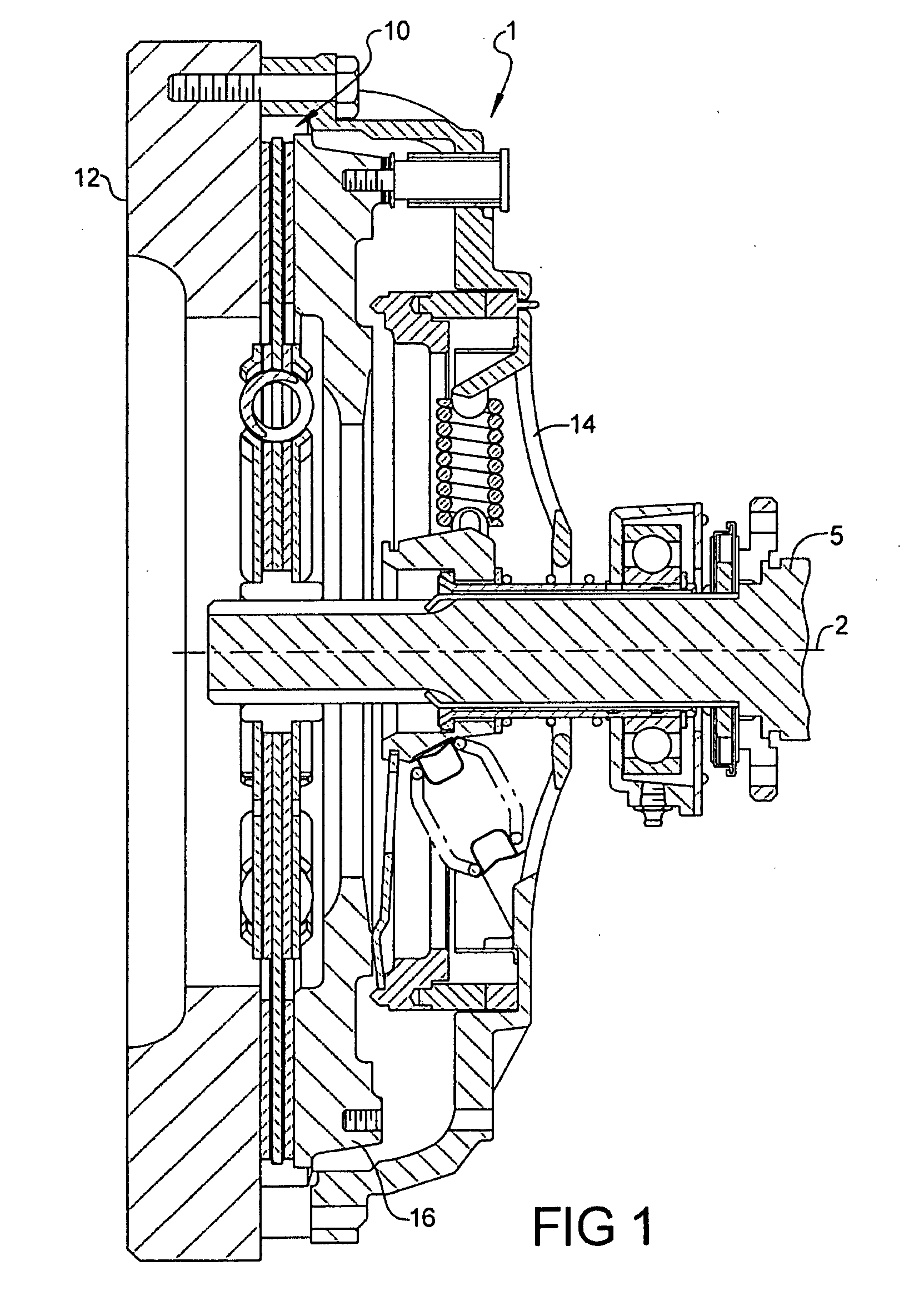
[0020]Referring now to FIG. 1, a cross-sectional view of a representative friction torque device 1 into which the present invention may be incorporated is shown. The friction torque device 1 comprises a driving member 12 having an axis of rotation 2. A cover 14 is coupled to the driving member 12 for rotation therewith. A pressure plate 16 is coupled to the cover 14 for rotation therewith. A driven disc 10 is coupled to an axially extending driven shaft 5 for rotation therewith. Although driven disc 10 is shown splined to driven shaft 5, it should be apparent to those skilled in the art that any suitable means known in the art may be substituted for a splined coupling. The driven disc 10 is interposed between the driving member 12 and the pressure plate 16.

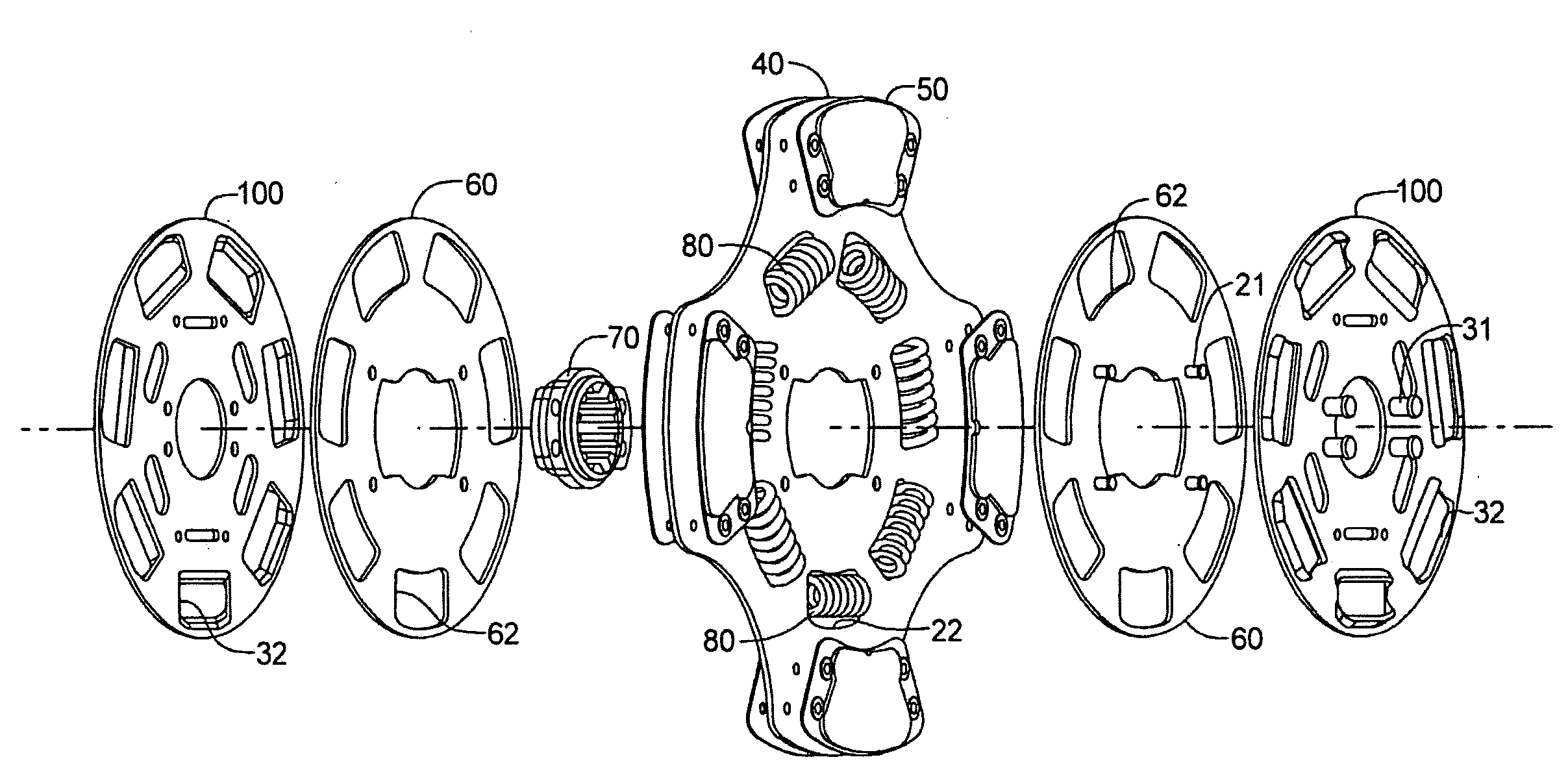
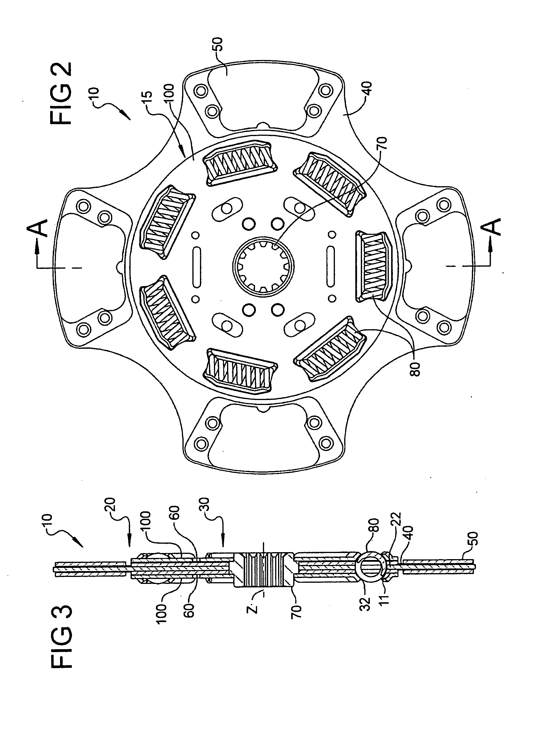
[0021]Referring now to FIGS. 2 and 3, representative driven disc 10 is shown. Driven disc 10 is not intended to show the only possible application of the present invention. Driven disc 10 incorporates a torsional damper 15. Driven...


PUM


Abstract

A torsional damper with a hub assembly and a disc assembly has coil springs disposed therebetween. The coil springs are disposed in pockets defined in part by apertures in opposed cover plates. The apertures have sharply angled end portions providing deflection relief near the ends of the coil springs.

Description

RELATED APPLICATIONS[0001]This continuation in part application claims the benefit of Provisional Application 60 / 965,271, filed Aug. 17, 2008 the disclosure of which is incorporated herein by reference.FIELD OF THE INVENTION[0002]The present invention relates to the field of torsional vibration dampers in general, and more specifically, to friction clutches having torsional vibration dampers.BACKGROUND OF THE INVENTION[0003]Torsional vibrations are the rotational irregularities of a rotatingly driven component. In a vehicle drivetrain, torsional vibrations are caused by the forces generated within a combustion engine by the combustion of gases during the periodic combustion process. Torsional vibrations of the second or third order which originate from the engine, as a result of the ignition frequency of four or six cylinder engines, respectively, are predominant in the vehicle driveline. Torsional vibrations not only emanate from the engine power pulses but also from torque spikes ...

Claims


Application Information

Patent Timeline
Patent Type & Authority Applications(United States)
IPC IPC(8): F16D13/68
CPCF16F15/12313
Inventor BASSETT, MICHAEL L.
Owner EATON INTELLIGENT POWER LIMITED
Why Eureka
Try Eureka