
Damper root ring

Active Publication Date: 2009-02-19
AEROJET ROCKETDYNE OF DE
View PDF13 Cites 11 Cited by
  • Summary
  • Abstract
  • Description
  • Claims
  • Application Information

AI Technical Summary

Benefits of technology

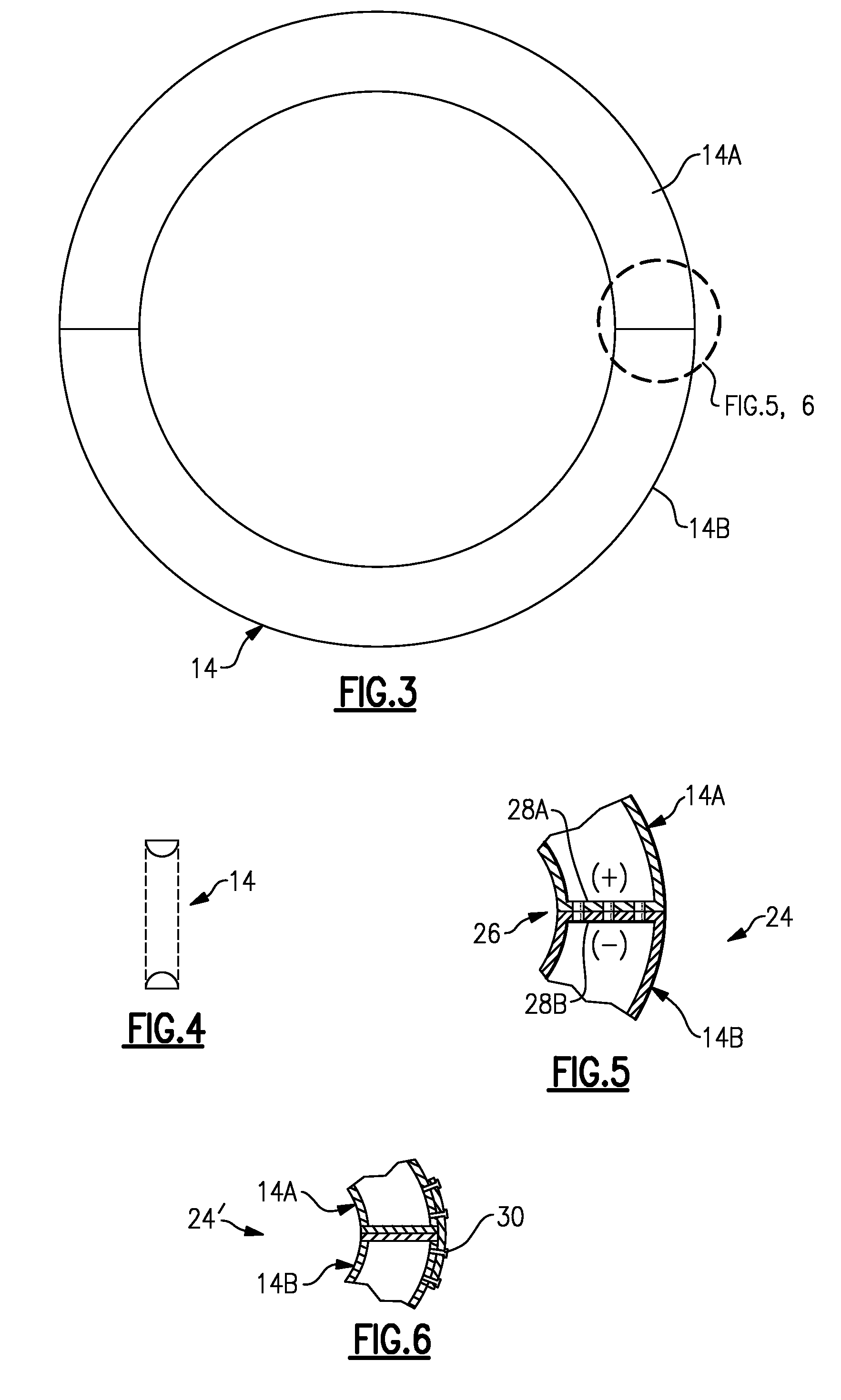
[0004]The damper according to the present invention provides damping to the motion of a bellows type expansion joint. The damper is located at the root region of the convolutions and is at least partially filled with a damping medium to provide damping therefor. The damping medium may include particles with or without an entrapped fluid to provide particle damping. The damper may be manufactured in segments which have an attachment structure therebetween to facilitate retrofitting of the damper to various conduits that are experiencing or are expected to experience flow induced vibration.
[0005]The present invention therefore provides a damper to minimize undesirable structural response in a bellows type expansion joint.

Problems solved by technology

Fluids which flow along internal convolutions of the bellows expansion joint may produce flow disturbances.
Flow induced vortex shedding is an unsteady flow that may occur at certain fluid flow velocities.
The flow disturbances and structural response may result in feedback which may cause large displacements adjacent the bellows convolutions and high cycle fatigue.
Over a period of time the fatigue may ultimately produce failure in the bellows type expansion joint.

Method used


Image

  • Damper root ring
  • Damper root ring
  • Damper root ring

Examples


Embodiment Construction

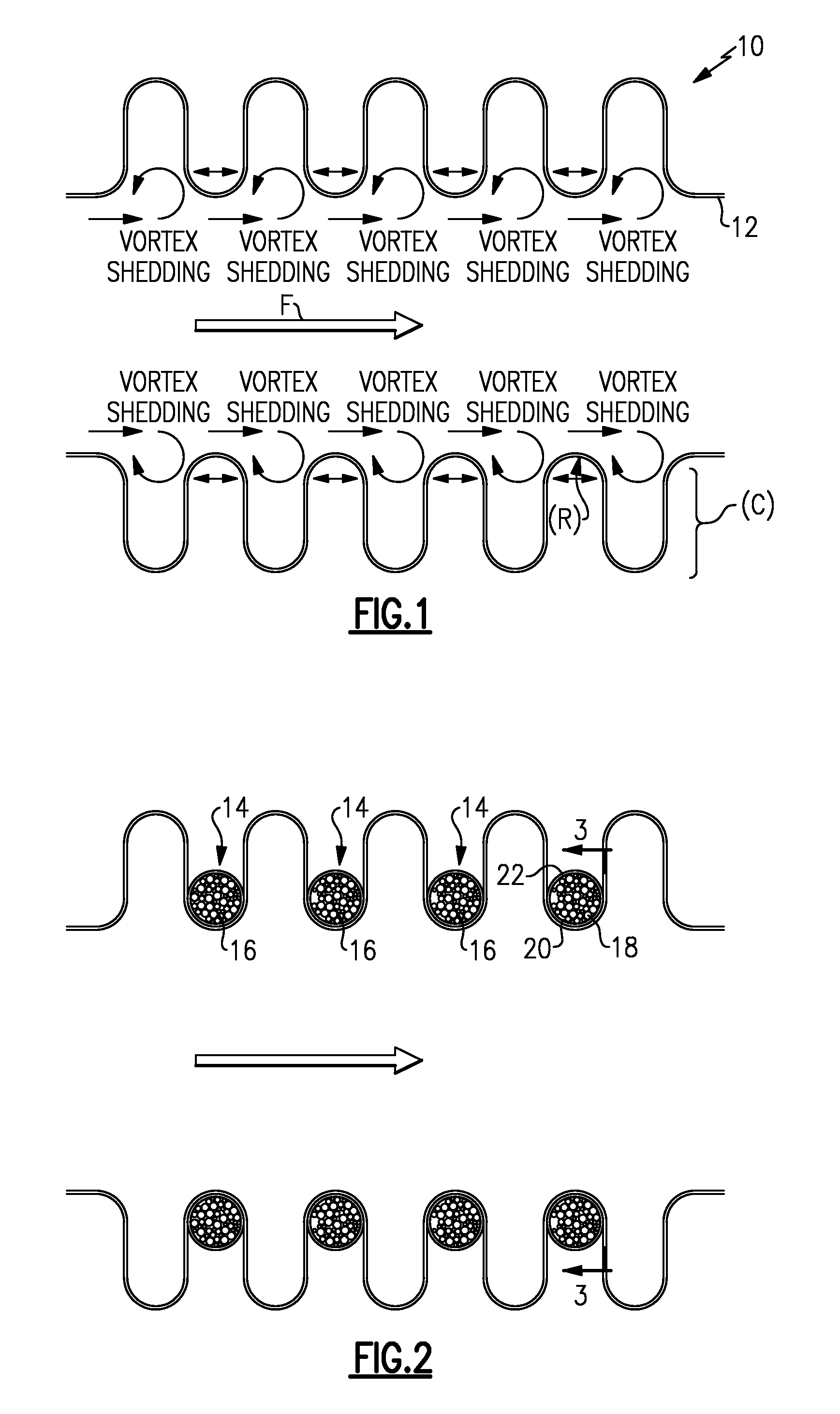
[0013]FIG. 1 schematically illustrates a bellows-type expansion joint 10 located within a conduit 12 typical of a pipe or duct system which communicates a fluid flow (illustrated schematically by arrow F).

[0014]Flow induced vortex shedding is an unsteady flow that may occur at certain fluid flow velocities. Flow induced vortex shedding may cause an alternating force adjacent a root region R of one or more convolutions C. Eventually, if the frequency of vortex shedding matches the resonant frequency of the structure, the structure may begin to resonate and the structure's movement can become self-sustaining which may ultimately result in failure.

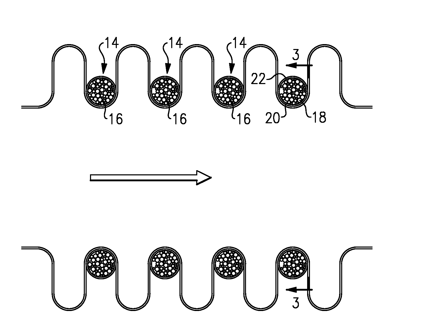
[0015]Referring to FIG. 2, resonance within the conduit 12 is minimized or eliminated by attachment of a damper 14 at the root region R of one or more convolutions C. The damper 14 is a hollow generally annular member (FIG. 3) which is fit to the root region R to damp motion often cased by flow induced vibration. It should be understood that ...


PUM

PropertyMeasurementUnit
Structureaaaaaaaaaa
Magnetismaaaaaaaaaa

Abstract

A damper that provides damping to the motion caused by flow induced vibration of a bellows type expansion joint. The damper is at least partially filled with a damping medium and located at a root region of the bellows type expansion joint convolutions. The damper is manufactured in segments which have an attachment structure therebetween to facilitate retrofitting of the damper to various conduits that are experiencing or are expected to experience flow induced vibration.

Description

BACKGROUND OF THE INVENTION[0001]The present invention relates to a damper, and more particularly to a damper root ring for a bellows type expansion joint.[0002]Bellows type expansion joints are often utilized in piping and ducting systems adjacent to an unstable flow regime. Fluids which flow along internal convolutions of the bellows expansion joint may produce flow disturbances. One type of flow disturbance is flow induced vortex shedding. Flow induced vortex shedding is an unsteady flow that may occur at certain fluid flow velocities. The flow disturbances and structural response may result in feedback which may cause large displacements adjacent the bellows convolutions and high cycle fatigue. Over a period of time the fatigue may ultimately produce failure in the bellows type expansion joint.[0003]Accordingly, it is desirable to provide a damper to minimize undesirable structural response in a bellows type expansion joint.SUMMARY OF THE INVENTION[0004]The damper according to t...

Claims


Application Information

Patent Timeline
IPC IPC(8): F16L27/11F17D1/16
CPCF16L55/0335Y10T29/49877F16L55/035Y10T137/0391
Inventor CIPRA, DALE O.
Owner AEROJET ROCKETDYNE OF DE
Learn More