Image pickup apparatus and signal processing method

Active Publication Date: 2009-02-19
FUJIFILM CORP
View PDF11 Cites 73 Cited by
  • Summary
  • Abstract
  • Description
  • Claims
  • Application Information

AI Technical Summary

Benefits of technology

[0007]It is therefore an object of the invention to provide an image pickup apparatus capable of faithfully and reliably reproducing a subject imag

Problems solved by technology

However, since the low sensitive light reception cell has S/N ratio lowered relative to the high sensitive light reception cell, if they are partially combined into one, an unnatural image results.
Although the low sensitive light reception cell and the high sensitive light reception cell are close to each other, they are placed at different positions and thus the picked

Method used


Image

  • Image pickup apparatus and signal processing method
  • Image pickup apparatus and signal processing method
  • Image pickup apparatus and signal processing method

Examples


first embodiment

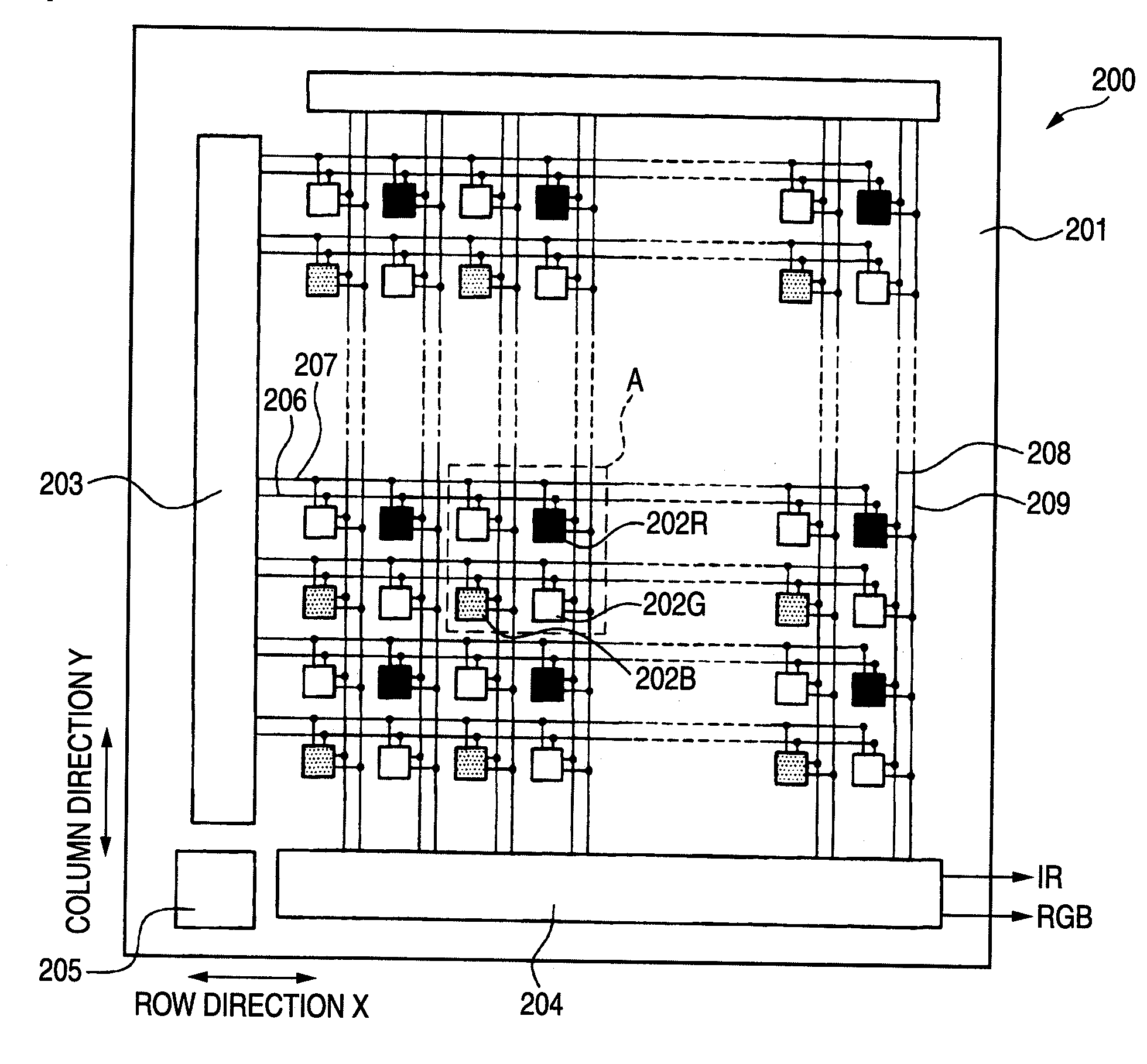
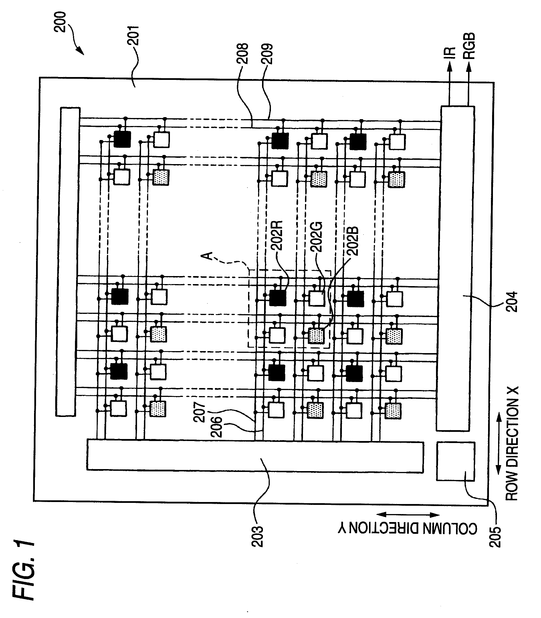
[0024]FIG. 1 is a plan schematic drawing to show the schematic configuration of a solid-state image sensing device of a first embodiment of the invention.

[0025]A solid-state image sensing device 200 shown in FIG. 1 includes three types of pixels of pixels 202R capable of outputting an R signal responsive to R light of incident light, pixels 202G capable of outputting a G signal responsive to G light of incident light, and pixels 202B capable of outputting a B signal responsive to B light of incident light, and the pixels are arranged two-dimensionally in a row direction X on a substrate 201 of silicon, etc., and a column direction Y orthogonal to the row direction X.

[0026]As shown in FIG. 1, the pixel array of the solid-state image sensing device 200 is an alternating pattern of a GR pixel row of a pixel row of an alternating pattern of pixels 202G and 202R in the row direction X and a BG pixel row of a pixel row of an alternating pattern of pixels 202B and 202G in the row direction...

second embodiment

[0088]The general configuration of a digital camera described in a second embodiment of the invention is almost the same as that shown in FIG. 3 except the configurations of solid-state image sensing device 200 and digital signal processing section 17.

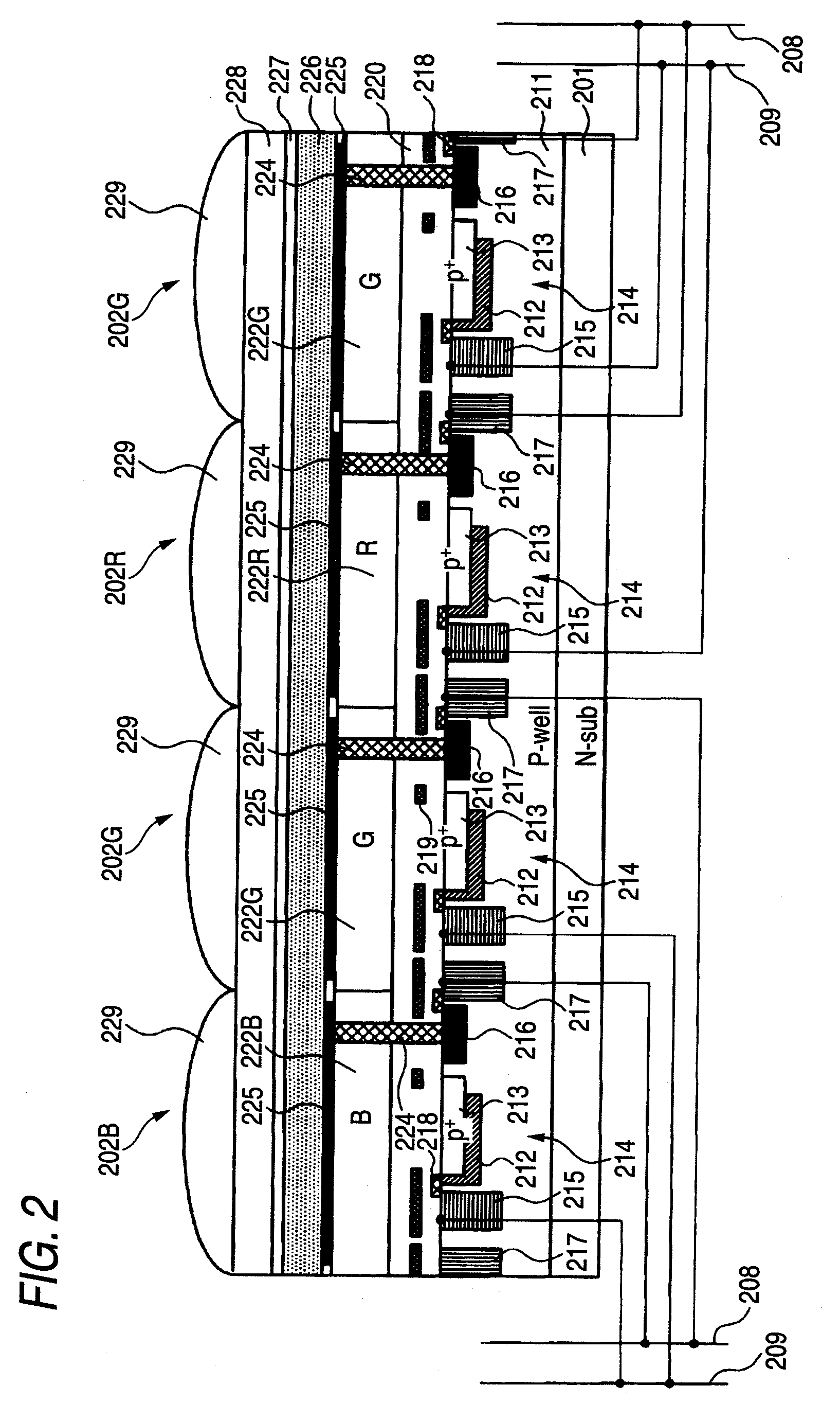
[0089]A solid-state image sensing device 200 of the digital camera of the second embodiment uses a photoelectric conversion material for absorbing light in a wave range of a part of G light (about 480 nm to about 520 nm) (which will be hereinafter referred to as emerald (E) light) and generating a charge responsive to the E light as a photoelectric conversion film 226. According to the configuration, E image data containing only an E component can be generated using an output signal of an organic photoelectric conversion element and RGB color image data improved in color reproducibility can be generated using an output signal of a photoelectric conversion element 214 and the output signal of the organic photoelectric conversion element...

third embodiment

[0103]The general configuration of a digital camera described in a third embodiment of the invention is almost the same as that shown in FIG. 3 except the configurations of solid-state image sensing device 200 and digital signal processing section 17.

[0104]The solid-state image sensing device 200 of the digital camera of the third embodiment has a configuration wherein the pixels 202G of the GR pixel row shown in FIG. 1 are changed to pixels 202B, the pixels 202G of the BG pixel row shown in FIG. 1 are changed to pixels 202R, and a photoelectric conversion material for absorbing G light and generating a charge responsive to the G light is used as a photoelectric conversion film 226. According to the configuration, monochrome image data containing only a G component can be generated using an output signal of an organic photoelectric conversion element and RGB color image data can be generated using an output signal of a photoelectric conversion element 214 and the output signal of th...


PUM


Abstract

An image pickup apparatus includes: a solid-state image sensing device that includes a plurality of pixels, each of the pixels including: a photoelectric conversion film; and a photoelectric conversion element that is formed in the semiconductor substrate below the photoelectric conversion film, are made up of at least three types of photoelectric conversion elements for detecting light in different wave ranges, of visible light, and absorbs light in a wave range different from the wave ranges detected in the at least three types of photoelectric conversion elements and generates a charge responsive to the absorbed light, the image pickup apparatus further including: a monochrome image data generation unit; a color image data generation unit; and a record image data generation unit.

Description

BACKGROUND OF THE INVENTION[0001]1. Field of the Invention[0002]This invention relates to an image pickup apparatus including a solid-state image sensing device having a large number of pixels.[0003]2. Background Art[0004]In recent years, various image pickup apparatus capable of picking up an image in a wide dynamic range have been proposed (For example, refer to JP-A-2004-048445 (the term “JP-A” as used herein means an “unexamined published Japanese patent application”)). JP-A-2004-048445 discloses the following image synthesis method: a high sensitive image and a low sensitive image less different in time and space are acquired using a solid-state image sensing device wherein each light reception cell is divided into a high sensitive light reception area and a low sensitive light reception area, an image quality degradation area of white splattering, black batter, etc., is automatically determined from one of the two images, the corresponding area is cut out from the other image ...

Claims


Application Information

Patent Timeline
IPC IPC(8): H04N5/335H04N5/353H04N5/3745H04N9/07
CPCH04N5/23232H04N5/235H04N5/2357H04N2209/047H04N9/045H04N9/07H04N5/35545H01L27/14627H01L27/14647H01L27/14621H04N23/951H04N23/70H04N23/745H04N25/581H04N23/843H04N25/134H04N23/12
Inventor OTA, MOTOARI
Owner FUJIFILM CORP
Why Eureka
Try Eureka