Packet transfer control device and mobile node

a control device and packet technology, applied in the field of communication control methods, can solve problems such as failure or trouble in the communication performed by using network, and packet loss or time delay, so as to achieve the effect of suppressing packet loss and intentionally delaying the packet transfer to the mobile nod

Inactive Publication Date: 2009-02-19
PANASONIC CORP
View PDF7 Cites 117 Cited by
  • Summary
  • Abstract
  • Description
  • Claims
  • Application Information

AI Technical Summary

Benefits of technology

[0045]With the arrangement as described above, the buffering can be performed on the packet on the network side by the packet transfer between a plurality of home agents. As a result, the transfer of the packet to the mobile node can be intentionally delayed. Even when the mobile node is temporarily in unreachable state, for instance, packet loss can be suppre...

Problems solved by technology

In the past, various causes have been known, which may induce failure or trouble in the communication performed by using network.
In particular, when a node (radio communication node) is connected to Internet via radio communication, problems including packet loss or time delay may arise from the reasons such as the changes in electric wave conditions.
However, the two methods as described above relate to retransmission control on end-to-end basis, and although the packet loss can be improved, retransmission delay (delay in the retransmission control) may occur when a source located at the remotest position from the receiving node of the packet executes the retransmission.
However, the capacity to be buffered by a single router for the retransmission is limited.
In case buffer capacity of the router to carry out the buffering is relatively lower compared with the amount of the packets to be buffered, the router cannot buffer all packets, which require the buffering.
This results in the loss of packet.
As a result, the packet to the care-of address before the moving of MN cannot reach MN as originally aimed even when it is retransmitte...

Method used


Image

  • Packet transfer control device and mobile node
  • Packet transfer control device and mobile node
  • Packet transfer control device and mobile node

Examples


1st embodiment

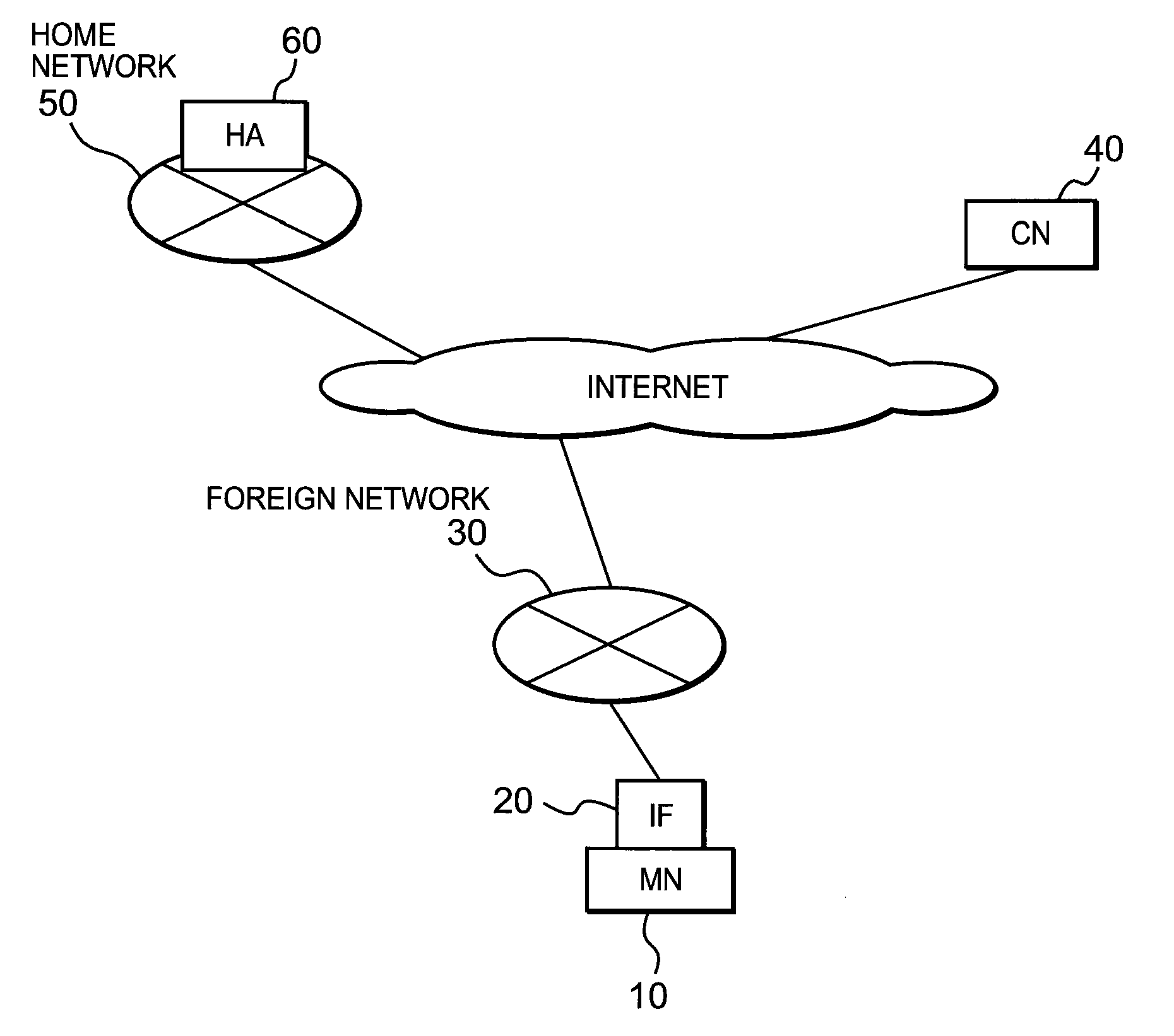
[0061]First, description will be given on the first embodiment of the invention. FIG. 1 shows an example of network arrangement in the first embodiment of the invention. In FIG. 1, MN 10 can utilize HA 60 in a home network 50 as its own home agent. A home address (HoA1) is assigned to MN 10 from the home network 50, and this HoA1 is controlled by HA 60. In FIG. 1, MN 10 is connected to a foreign network 30 via an interface (IF) 20, and CoA1 is assigned from the foreign network 30. On the other hand, it is supposed that the communication to and from CN 40 is performed via HA 60 by using HoA1.

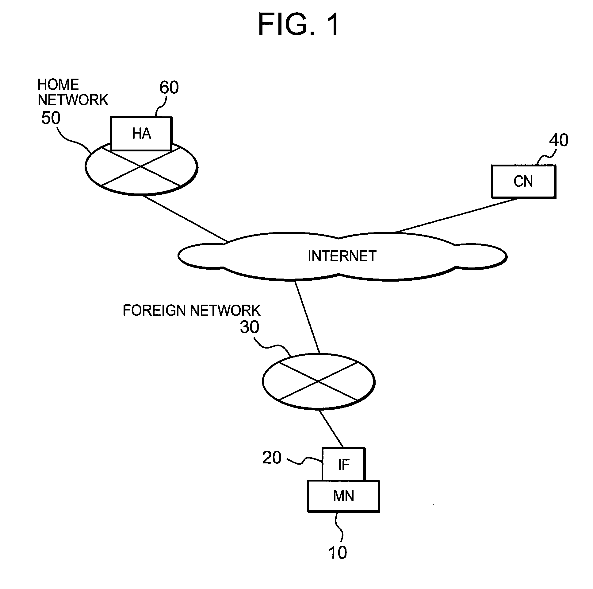
[0062]Next, description will be given on an arrangement of MN 10 in the first embodiment of the invention. FIG. 2 shows an example of arrangement of MN 10 in the first embodiment of the invention. In FIG. 2, MN 10 has a transmitting / receiving unit 101, a binding information notifying message generating unit 102, a binding information control unit 103, a buffering request judging unit 104, a flow ...

2nd embodiment

[0106]Next, description will be given below on a second embodiment of the invention. FIG. 7 shows an example of network in the prevent invention. In FIG. 7, MN 10 can utilize HAs (HA 60 and HA 80), which are present in a plurality of home networks (home networks 50 and 70) respectively. Home addresses (HoA1 and HoA2) of the home networks 50 and 70 are assigned to MN 10 respectively, and these home addresses HoA1 and HoA2 are controlled by HAs (HA 60 and HA 80) respectively. It is supposed in FIG. 7 that MN 10 is connected to the foreign network 30 via an interface (IF) 20 and CoA1 is assigned from the foreign network 30, and that communication via HA 60 is performed by using HoA1 for the communication with CN 40.

[0107]The number of interfaces used by MN 10 is not limited to one, and two or more interfaces may be used. In this case, two or more care-of addresses may be associated with each of HoA1 and HoA2 respectively. Also, the number of HAs (HA 60 and HA 80) usable by MN 10 is not...

3rd embodiment

[0161]Next, description will be given on a third embodiment of the invention. The third embodiment of the invention is basically a combination of the first embodiment and the second embodiment of the invention. In the third embodiment, actual example of the network arrangement will be described with the network arrangement shown in FIG. 7 as the precondition.

[0162]First, description will be given on the arrangement of MN 10 in the third embodiment of the invention. FIG. 11 shows an example of arrangement of MN 10 in the third embodiment of the invention. In FIG. 11, MN 10 comprises a transmitting / receiving unit 301, a binding information notifying message generating unit 302, an HoA1 binding information control unit 303, an HoA2 binding information control unit 304, a pre-transfer buffering request judging unit 305, a flow information notifying message generating unit 306, a home address association judging unit 307, a flow information control unit 308, and a buffering request judgi...


PUM


Abstract

A technique is disclosed, by which it is possible to perform retransmission control of a packet effective for a mobile node in a home agent. According to this technique, after being intercepted, among the packets encapsulated and transmitted and addressed to MN 10, MN 10 selects a packet to be transferred to a specific care-of address at HA, a packet having a specific flow information, or a packet transmitted to a specific correspondent node (e.g. CN 40). Then, MN 10 requests HA to perform buffering on the selected packets when the selected packets are to be transferred. As a result, even when the connection of MN is turned to unstable and the packet cannot reach MN from HA, HA can transfer the packet currently in buffering. This makes it possible to reduce the delay of the packet to reach MN compared with a case where the packet is retransmitted from CN.

Description

TECHNICAL FIELD[0001]The present invention relates to a communication control method for controlling communication by using Internet protocol (IP). In particular, the invention relates to a communication control method for buffering control and retransmission control of IP packet.BACKGROUND ART[0002]In the past, various causes have been known, which may induce failure or trouble in the communication performed by using network. In particular, when a node (radio communication node) is connected to Internet via radio communication, problems including packet loss or time delay may arise from the reasons such as the changes in electric wave conditions.[0003]To overcome the above problems, the Non-Patent Document 1 as given below describes a TCP (Transmission Control Protocol) layer of a source node (a transmission source node), and this TCP defines the retransmission of a packet when there is no acknowledgment (ACK) from a correspondent node to the transmitted data packet. Also, the TCP ...

Claims


Application Information

Patent Timeline
IPC IPC(8): H04W36/00H04L12/911H04W28/14H04W40/34H04W80/04
CPCH04L1/1874H04W80/04H04W28/14H04W8/26
Inventor ASO, KEIGO
Owner PANASONIC CORP
Why Eureka
Try Eureka