
Transmitting apparatus, receiving apparatus, and wireless communication method

Inactive Publication Date: 2009-02-19
PANASONIC CORP
View PDF4 Cites 46 Cited by
  • Summary
  • Abstract
  • Description
  • Claims
  • Application Information

AI Technical Summary

Benefits of technology

[0015]According to the present invention, it is possible to suppress intersymbol interference, further reduce the ratio of redundant components in a signal and improve the transmission efficiency.

Problems solved by technology

As a result, intersymbol interference which becomes an obstacle to development of high speed and wideband radio communication, occurs.

Method used


Image

  • Transmitting apparatus, receiving apparatus, and wireless communication method
  • Transmitting apparatus, receiving apparatus, and wireless communication method
  • Transmitting apparatus, receiving apparatus, and wireless communication method

Examples


embodiment 1

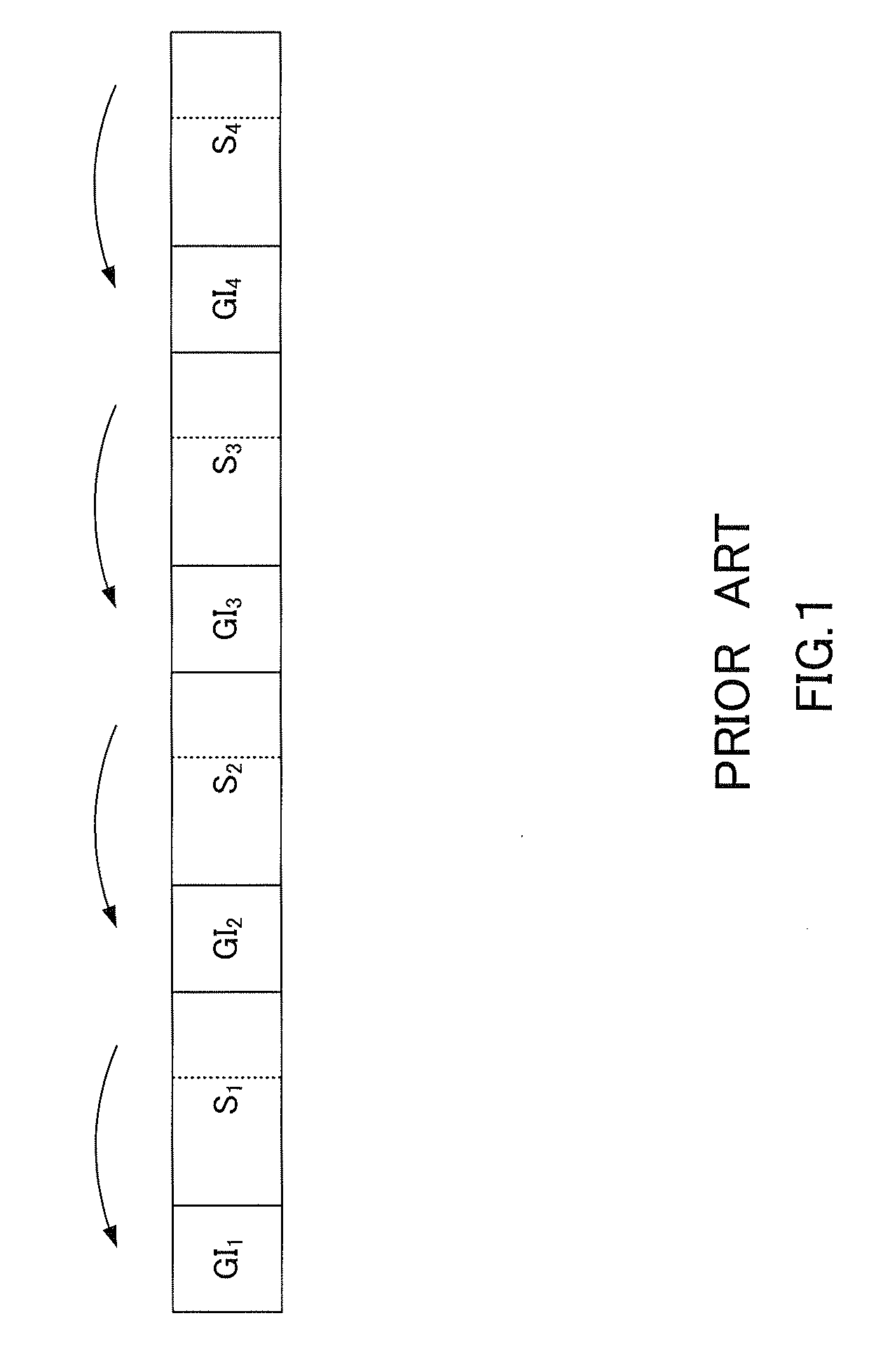
[0042]Features of Embodiment 1 of the present invention include, in an OFDM scheme, periodically inserting the same pilot symbol every plurality of information symbols and adding guard intervals only to the pilot symbols.

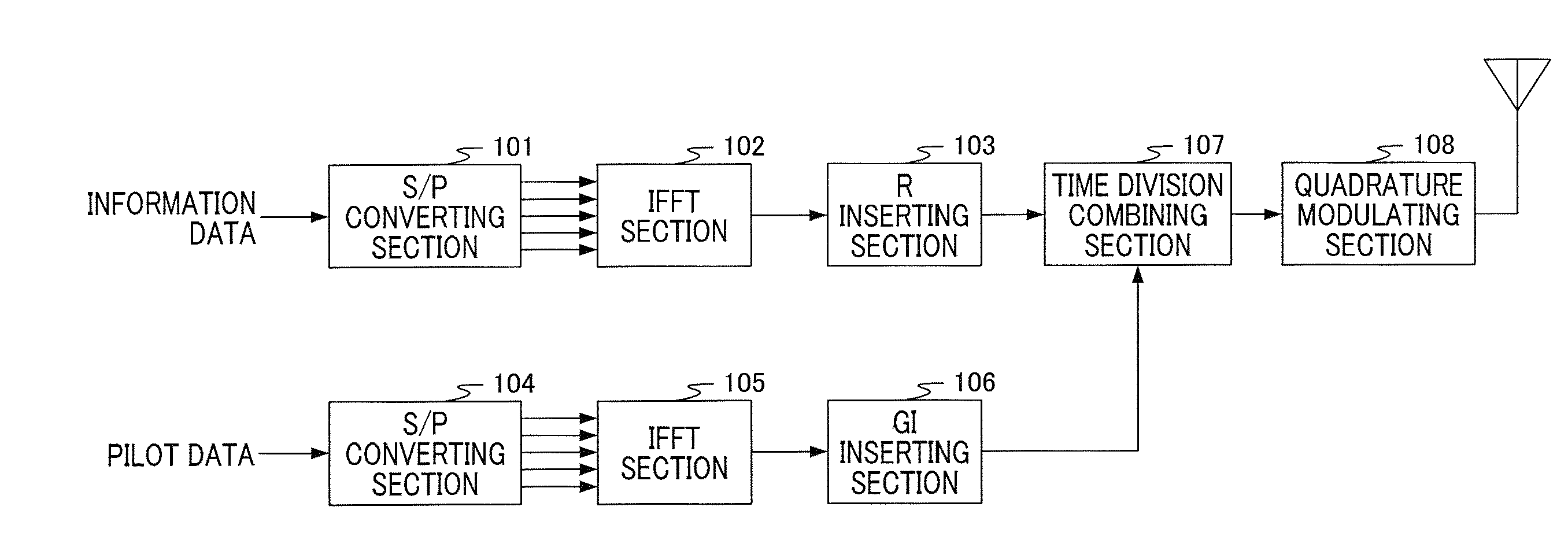
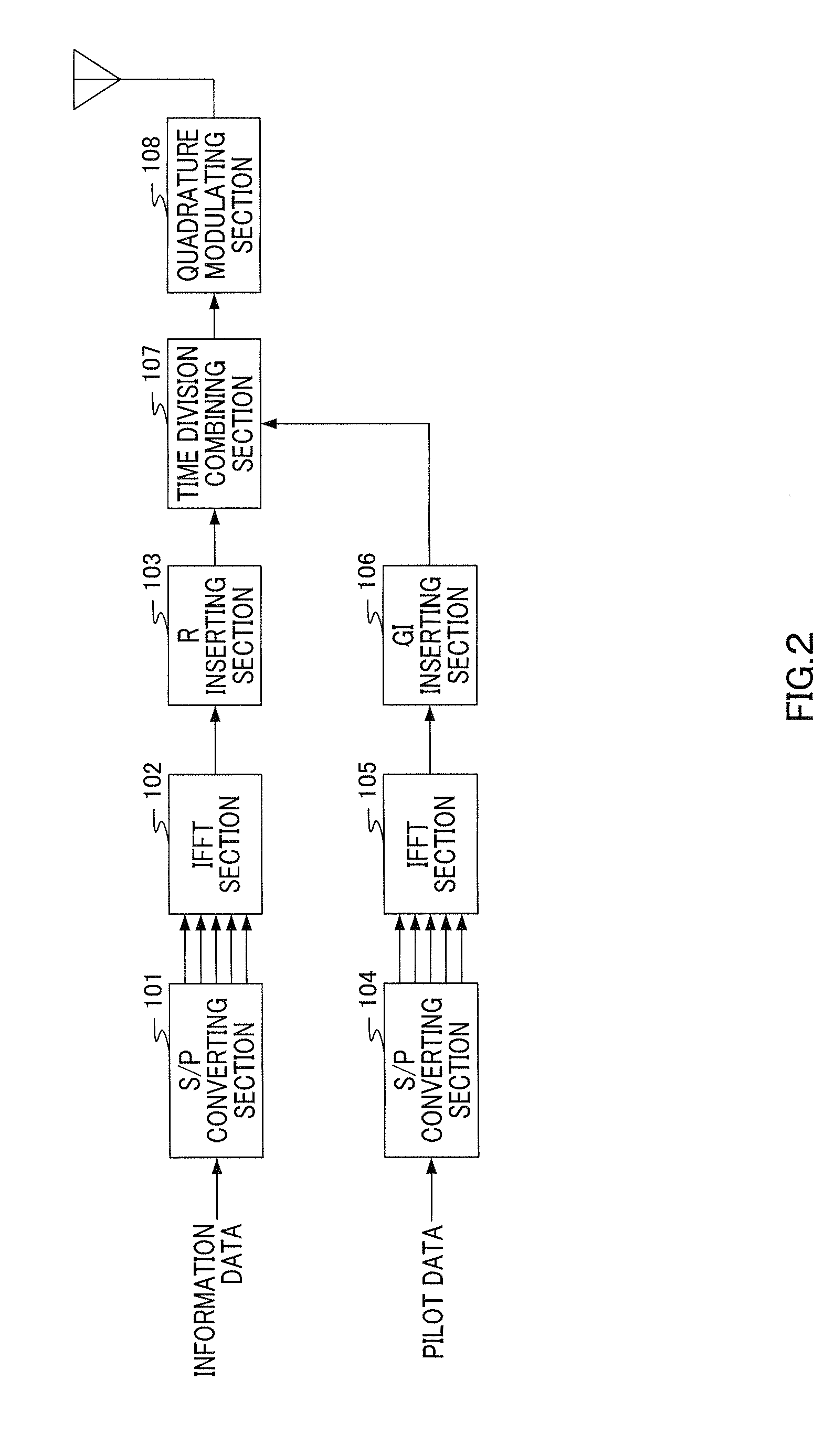
[0043]FIG. 2 is a block diagram showing the configuration of the main part of a transmitting apparatus according to Embodiment 1. The transmitting apparatus shown in FIG. 2 has S / P (Serial / Parallel) converting section 101, IFFT (Inverse Fast Fourier Transform) section 102, R (Ramp) inserting section 103, S / P converting section 104, IFFT section 105, GI (Guard Interval) inserting section 106, time division combining section 107 and quadrature modulating section 108.

[0044]S / P converting section 101 performs S / P conversion on information data and outputs the parallel data corresponding to the number of subcarriers to IFFT section 102.

[0045]IFFT section 102 assigns the parallel data to subcarriers whose frequencies are orthogonal each other, performs inverse fast Fourie...

embodiment 2

[0086]Features of Embodiment 2 of the present invention include, in an SC scheme, periodically inserting the same pilot symbol sequence every plurality of information symbols and adding guard intervals only to the pilot symbol sequences.

[0087]The configuration of the transmitting apparatus according to Embodiment 2 is a configuration where S / P converting sections 101 and 104, IFFT sections 102 and 105, and R inserting section 103 according to an OFDM scheme are removed from the transmitting apparatus according to Embodiment 1 (FIG. 2), and the configuration of each processing section is the same as that of Embodiment 1, and descriptions thereof will be omitted. However, in this embodiment, the guard interval is formed by replicating a predetermined number of symbols of the end of the pilot symbol at the head of a pilot symbol, and the signal having the frame configuration where an information symbol sequence follows a pilot symbol sequence is subjected to band limitation by a filter...

embodiment 3

[0103]Features of Embodiment 3 of the present invention include obtaining fine channel estimation values on the frequency axis not by interpolating the channel estimation values on the frequency axis on the receiving side, but by creating a delay profile corresponding to the overall long FFT target segment from the channel estimation values and performing quadrature transformation.

[0104]In Embodiments 1 and 2, interpolating section 209 of the receiving apparatus interpolates channel estimation values, and it is thereby possible to obtain fine channel estimation values on the frequency axis. In this case, “fine channel estimation values on the frequency axis” specifically refers to the channel estimation values corresponding to the number of samples which correspond to the long FFT target segment in the bandwidth used for communication. That is, in the frame configuration shown in FIG. 5B, for example, when the number of samples of a combination of one symbol and one ramping segment ...


PUM


Abstract

A transmitting apparatus, a receiving apparatus and a wireless communication method for suppressing interference between codes, while further reducing the ratio of redundant components occupying a signal to improve the transmission efficiency. The transmitting apparatus (100) transmits a signal having a frame structure in which a plurality of symbols follow a pilot symbol to which a guard interval has been added. In the receiving apparatus (200) that receives that signal, a long FFT target section acquiring part (202) acquires, from the received OFDM signal, a long FFT target section that is a target section in which delay waves are to be removed by use of a pilot symbol. A long FFT part (203) performs a fast Fourier transformation of the long FFT target section to convert it to a frequency domain signal. A frequency equalizing part (204) performs a frequency equalization of the long FFT target section by use of an interpolation result of communication line estimation value. A long IFFT part (205) performs an inverse fast Fourier transformation of the long FFT target section as frequency equalized to convert it back to a time domain signal.

Description

TECHNICAL FIELD[0001]The present invention relates to a transmitting apparatus, receiving apparatus and radio communication method, and more particularly, a transmitting apparatus, receiving apparatus and radio communication method used in a multipath environment.BACKGROUND ART[0002]In general, in radio communication of a multipath environment, the same signal is transmitted on a plurality of paths of different routes, and thereby, on the receiving side, a mixture of direct waves and delay waves is received. As a result, intersymbol interference which becomes an obstacle to development of high speed and wideband radio communication, occurs.[0003]For suppressing intersymbol interference, the OFDM (Orthogonal Frequency Division Multiplexing) scheme and SC (Single Carrier) scheme, which are referred to as block transmission schemes, have attracted attention in recent years. In these schemes, as shown in FIG. 1, for example, guard intervals GI1, to GI4 are inserted between symbols S1 to...

Claims


Application Information

Patent Timeline
IPC IPC(8): H04L27/28H04J99/00
CPCH04L5/0007H04L5/0048H04L25/022H04L2025/03522H04L25/03159H04L25/03891H04L2025/03414H04L25/0232
Inventor UESUGI, MITSURUOTA, EIJISUMASU, ATSUSHIEBIKO, KEISUKE
Owner PANASONIC CORP
Features
  • Generate Ideas
  • Intellectual Property
  • Life Sciences
  • Materials
  • Tech Scout
  • Unparalleled Data Quality
  • Higher Quality Content
  • 60% Fewer Hallucinations
Learn More