
Device for insertion guide and endoscope having the same

a technology of endoscope and insertion guide, which is applied in the field of insertion guide and endoscope having the same, can solve the problems of insufficient force of propulsion, difficult image recognition, and long time taken for exact insertion, and achieve the effect of facilitating the advance of the head portion and easy and efficient insertion with force of propulsion

Inactive Publication Date: 2009-02-19
FUJIFILM CORP
View PDF13 Cites 52 Cited by
  • Summary
  • Abstract
  • Description
  • Claims
  • Application Information

AI Technical Summary

Benefits of technology

[0010]In view of the foregoing problems, an object of the present invention is to provide a device for insertion guide and endoscope having the same, in which an insertion tube of the endoscope can be inserted easily and efficiently with force of propulsion even with a simple structure.
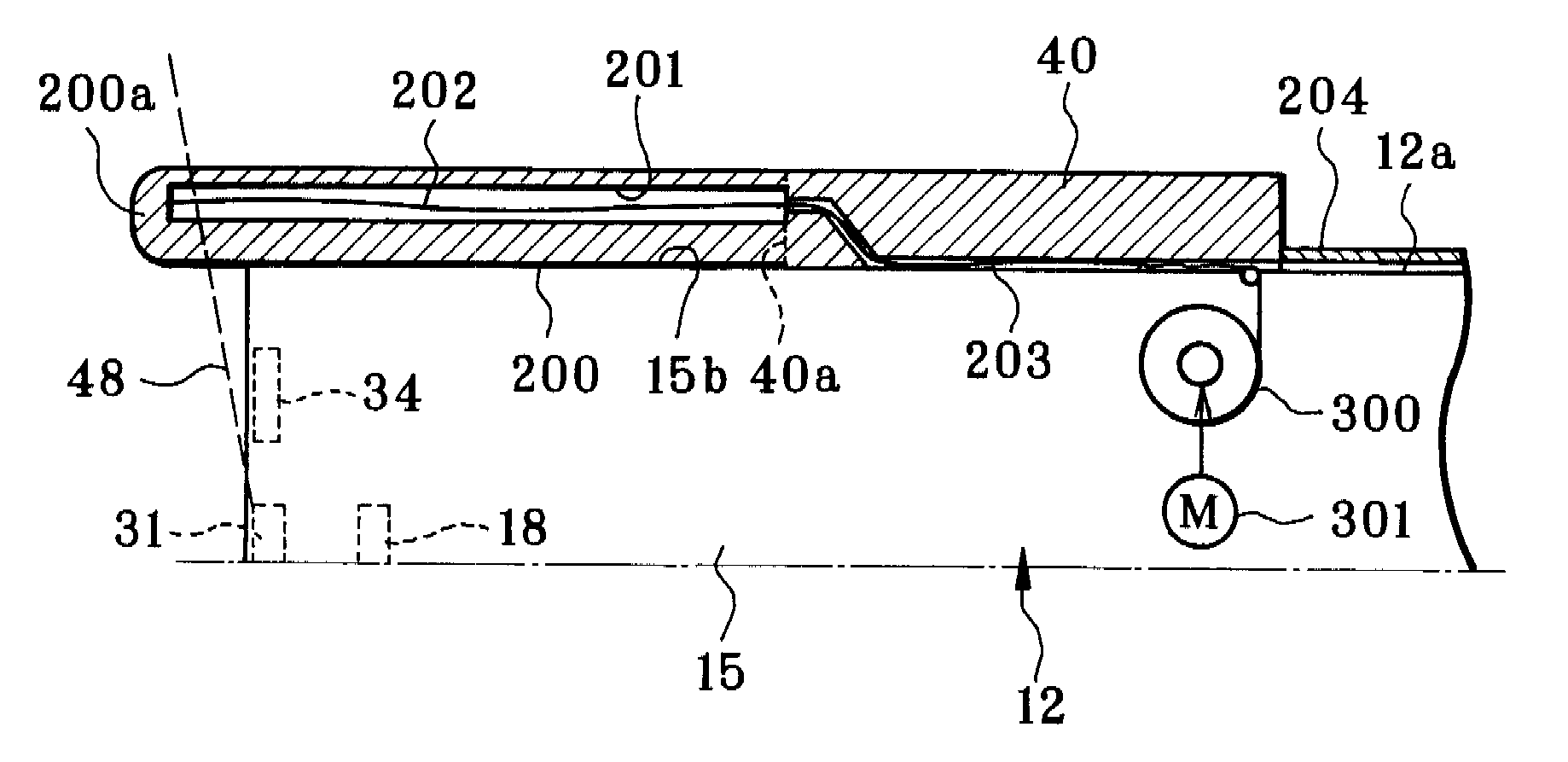
[0025]The endoscope includes a lighting window formed in the head portion. A light source applies light to an object in the body through the lighting window. Furthermore, an anti-reflection surface is formed with the propulsion fin portion, opposed to the head portion, for preventing reflection of the light.
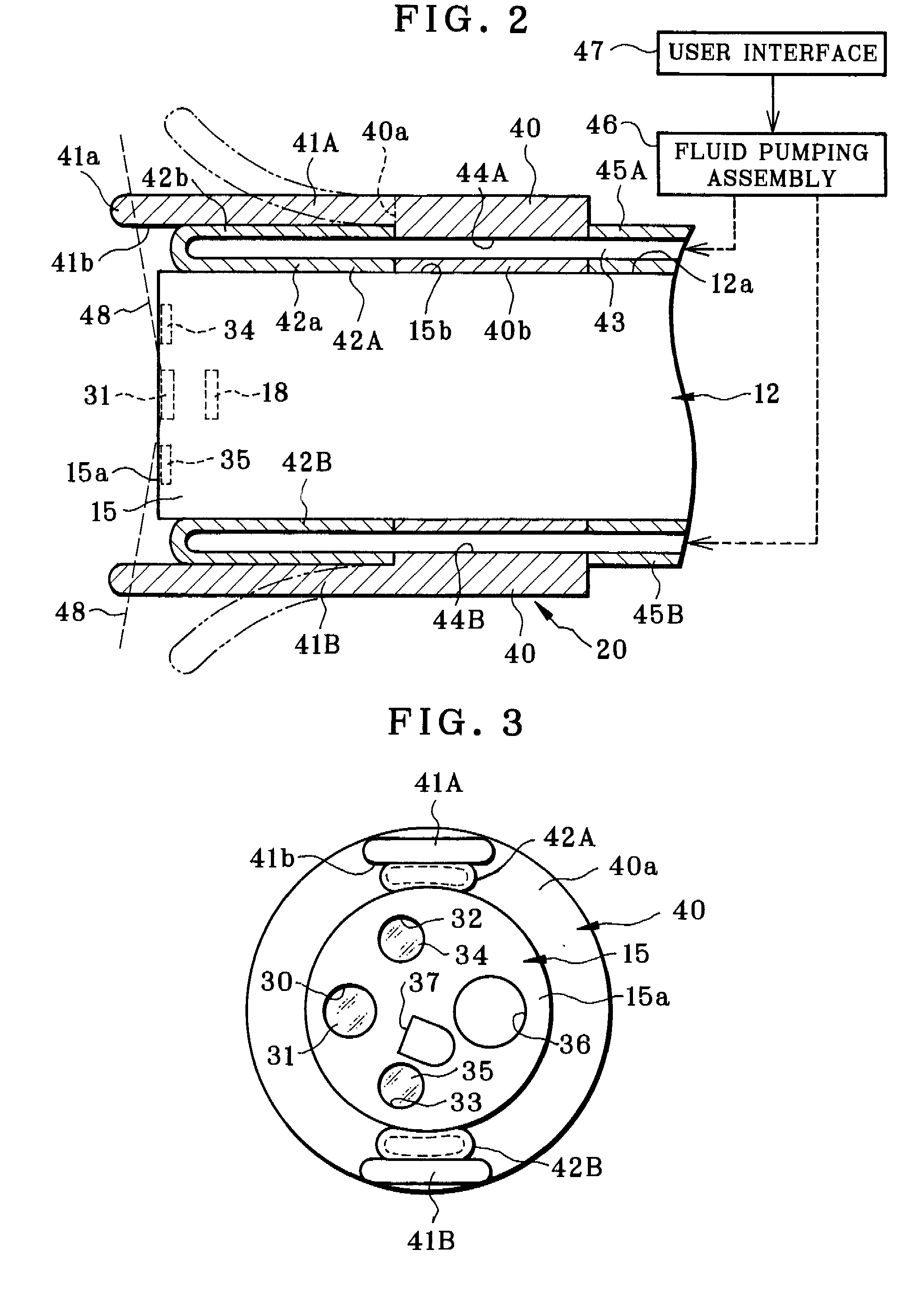
[0029]Consequently, an insertion tube of the endoscope can be inserted easily and efficiently with force of propulsion even with a simple structure, because the propulsion fin portion facilitates advance of the head portion of the endoscope.

Problems solved by technology

There is a problem in that an image is difficult to recognize because of the tilt of the head portion during the image pickup.
If an unskilled operator handles the endoscope, extremely long time may be taken for exact insertion, because he or she may miss the insertion direction.
However, it is supposed that no sufficient force of propulsion is available according to the techniques of U.S. Pat. No. 6,071,234 (corresponding to JP-A 11-342106), U.S.P. No. 2008 / 009675 (corresponding to JP-A 2006-230620), and U.S. Pat. No. 6,988,986 (corresponding to JP-A 2005-534367), because a slip is likely to occur between the intestinal wall and the insertion tube (with the endless belt, tube of propulsion, or the loop).
Should the endoscope such as a colonoscope be constructed for high friction according to those documents, the intestinal wall is very likely to be wounded.
There is no idea of utilizing an available type of the endoscope in a known form.
However, those documents do not disclose exertion of force of propulsion of the insertion tube.
However, the insertion direction of the insertion tube may be missed because the head portion or video imaging device or probe at a distal end is swung.
This structure also requires a complicated construction of the endoscope.

Method used


Image

  • Device for insertion guide and endoscope having the same
  • Device for insertion guide and endoscope having the same
  • Device for insertion guide and endoscope having the same

Examples


Embodiment Construction

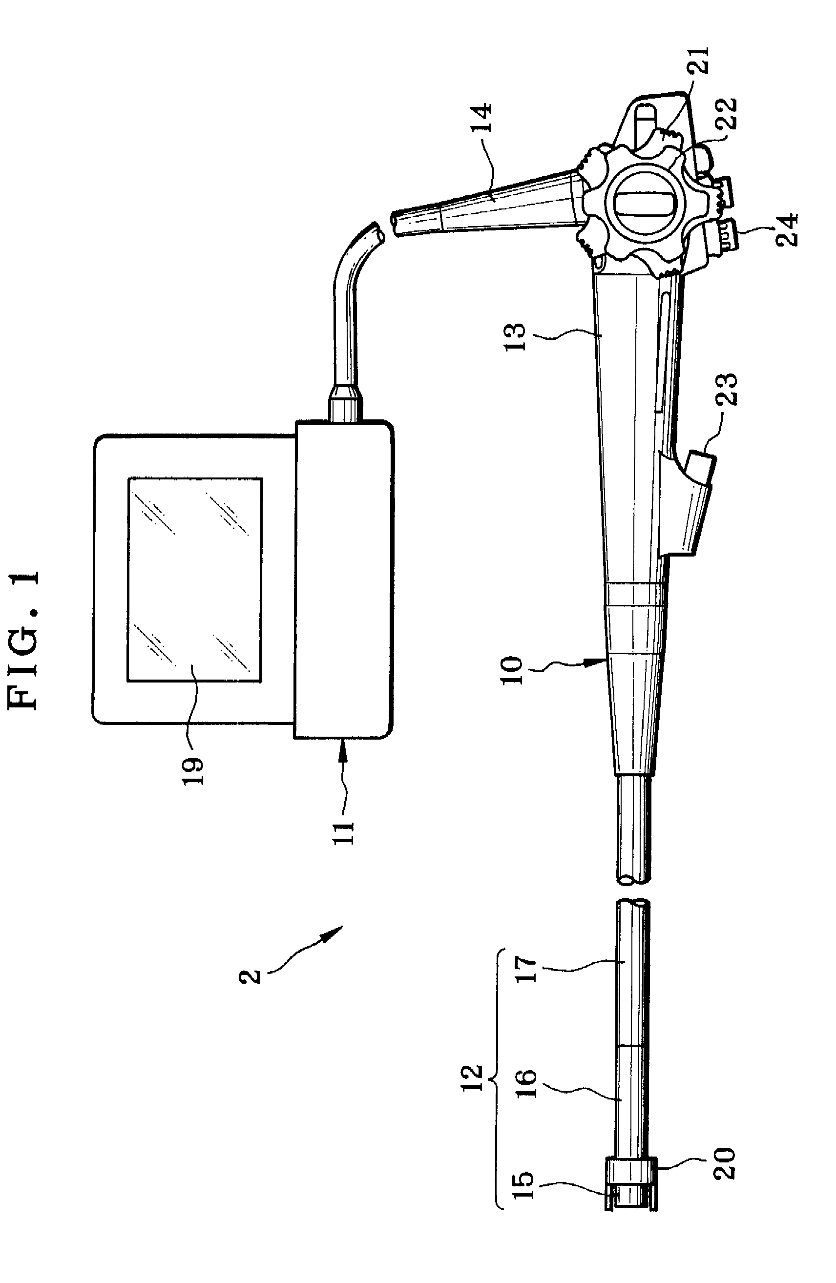
[0041]In FIG. 1, a colonoscopic system 2 as electronic endoscopic system includes a colonoscope 10 as electronic endoscope, a video processor 11 and a light source. The colonoscope 10 includes an insertion tube 12, a handle 13, and a cable 14. The handle 13 is a base from which the insertion tube 12 extends. The cable 14 extends for connection with the light source. A device for insertion guide 20 is attached to the colonoscope 10 for introducing access to a gastrointestinal tract of a patient's body in the medical diagnosis.

[0042]The insertion tube 12 includes a head portion 15 or video imaging device or probe at a distal end, a steering portion 16, and a flexible portion 17. The head portion 15 has a rigid body. In FIG. 2, an image pickup unit 18 or CCD image sensor is incorporated in the head portion 15 for image pickup of an object of interest in the gastrointestinal tract. Image data of the object is created by the image pickup unit 18, and is transmitted to the video processor...


PUM


Abstract

A colonoscope as an endoscope has an insertion tube for insertion in a patient's gastrointestinal tract. A head portion is disposed at an end of the insertion tube, for inspecting a large intestine. In combination with this, a device for insertion guide includes a base tube mounted on the head portion. Two propulsion fins are disposed on the base tube to extend in an axial direction of the head portion. A driving mechanism with balloons shifts the propulsion fins between closed and open positions. The propulsion fins, when in the closed position, are disposed to extend along the head portion, and when in the open position, are deployed in a radial direction by setting a distal fin end thereof away from the head portion, to propel the head portion inserted in the large intestine. Furthermore, the balloons set the propulsion fins in the open position alternately with one another.

Description

BACKGROUND OF THE INVENTION[0001]1. Field of the Invention[0002]The present invention relates to a device for insertion guide and endoscope having the same. More particularly, the present invention relates to a device for insertion guide and endoscope having the same, in which an insertion tube of the endoscope can be inserted easily and efficiently with force of propulsion even with a simple structure.[0003]2. Description Related to the Prior Art[0004]An endoscope such as a colonoscope is known in the field of medical instruments. An insertion tube is inserted in a small intestine, large intestine or the like in a gastrointestinal tract of a patient's body. An intestinal wall is reached through a tortuous path, and observed with the endoscope to diagnosis and treatment. A head portion or video imaging device or probe at a distal end is positioned on the insertion tube, and has an image pickup unit which creates image data of an image. While an operator observes the image, a steerin...

Claims


Application Information

Patent Timeline
IPC IPC(8): A61B1/04A61B1/06
CPCA61B1/00156G02B23/2476A61B1/31A61B1/0051
Inventor YAMAMOTO, SEIICHI
Owner FUJIFILM CORP
Learn More