Support system for a photovoltaic system

a photovoltaic system and support system technology, applied in the field of systems, can solve the problems of increasing the use of air conditioning, parking lots exposed, and capturing hea

Inactive Publication Date: 2009-02-26
ENVISION SOLAR INT
View PDF9 Cites 98 Cited by
  • Summary
  • Abstract
  • Description
  • Claims
  • Application Information

AI Technical Summary

Benefits of technology

[0007]Structurally, the rack and the photovoltaic cells may lie in the horizontal plane. However, the rack and photovoltaic cells may be inclined by 10° to face south to receive an optimal amount of solar energy (in the northern hemisphere). Alternatively, the rack may define a plurality of sections that, when erected, extend east-to-west. For such a rack, the sections and the photovoltaic cells are preferably inclined by 20° to face south.

Problems solved by technology

Further, the cars parked on exposed parking lots trap heat and require increased use of air-conditioning.

Method used


Image

  • Support system for a photovoltaic system
  • Support system for a photovoltaic system
  • Support system for a photovoltaic system

Examples


Embodiment Construction

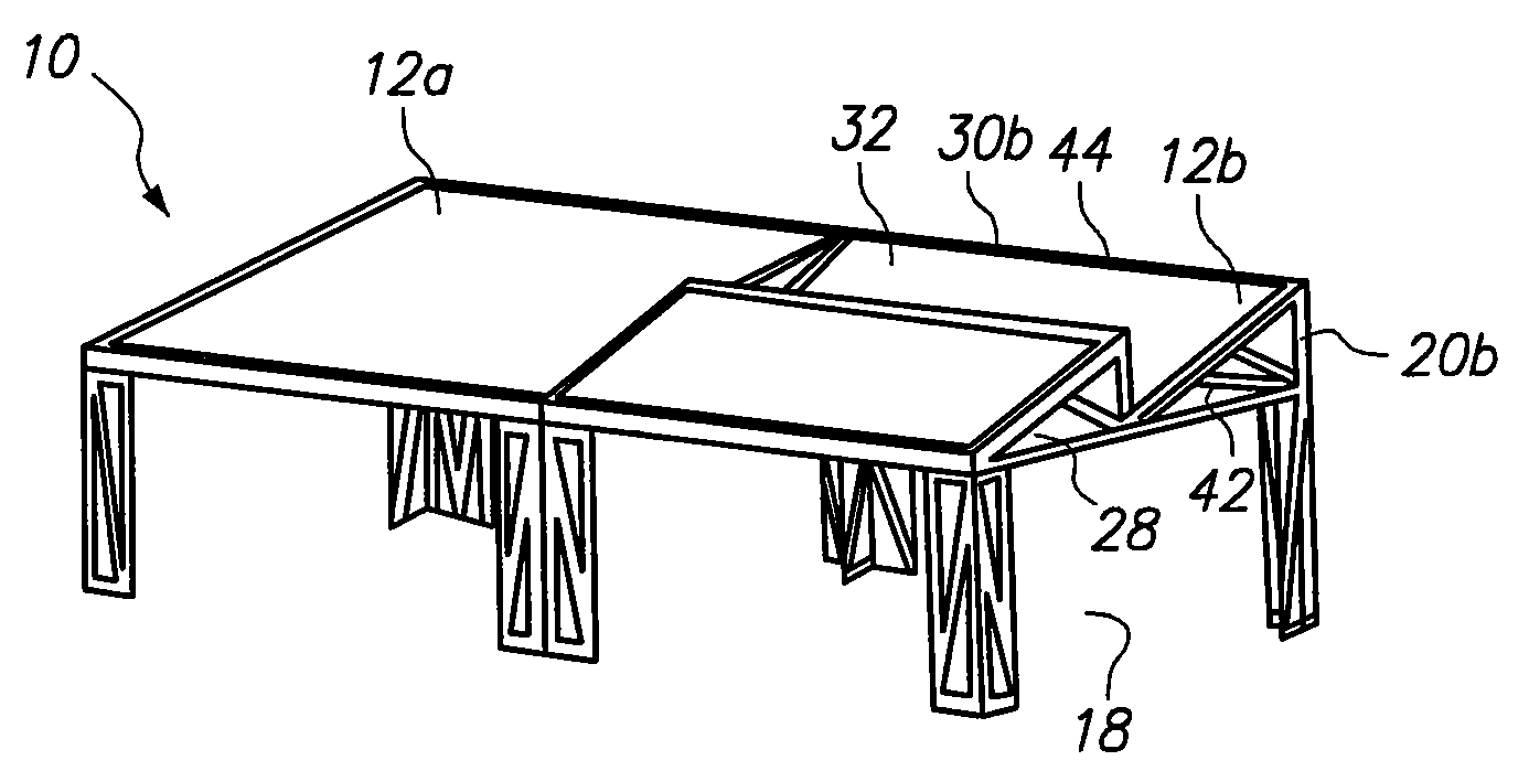
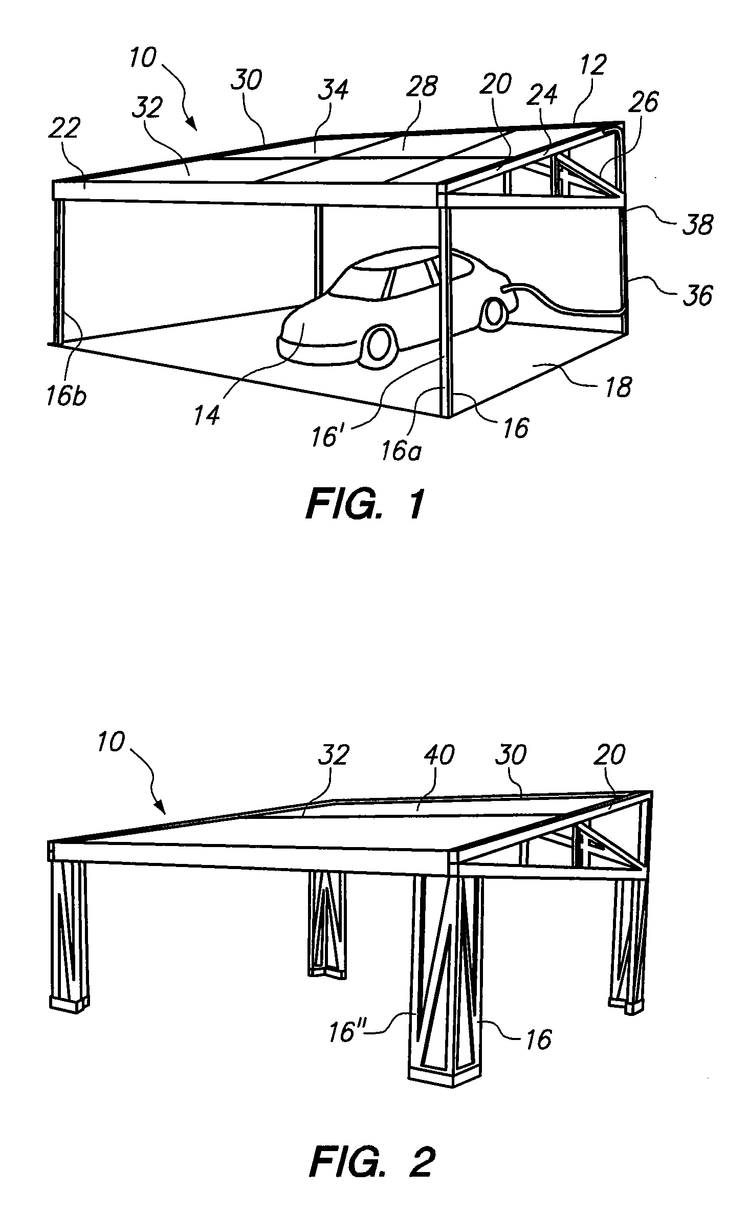
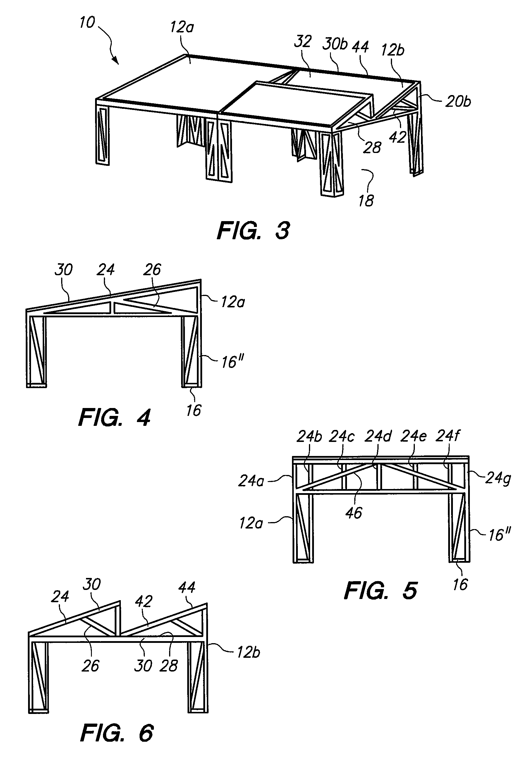
[0015]Referring initially to FIG. 1, a modular structure for supporting a photovoltaic system is shown and generally designated 10. In the embodiment shown in FIG. 1, the modular structure 10 serves as a carport 12 for housing a car 14. Structurally, the carport 12 is formed from four columns 16 that are distanced from one another to define an area 18. In FIG. 1, each column 16 is comprised of a single leg 16′. Further, the structure 10 includes a truss assembly 20 that is mounted to and suspended from the columns 16. As shown, the truss assembly 20 includes headers 22 that interconnect adjacent columns (e.g., 16a and 16b). Further, the truss assembly 20 includes rafters 24 and support members 26 to establish an open roof 28 at a desired incline. In the northern hemisphere, the roof 28 is preferably inclined at 10° and faces south.

[0016]In FIG. 1, a rack 30 is mounted on the truss assembly 20. Further, photovoltaic cells 32 are positioned in the rack 30. In FIG. 1, the photovoltaic ...


PUM


Abstract

A method and modular assembly provide shade and generate electricity using photovoltaic cells. In the method, a kit includes a plurality of columns, a truss assembly, a rack, and a plurality of photovoltaic cells for converting solar energy into electricity. First, four columns are erected at a distance from one another to define an area. Then, the truss assembly is suspended between the columns. Thereafter, the rack is mounted to the truss assembly to form an open roof. To enclose the roof, the photovoltaic cells are arranged on the rack to block sunlight to shade the area, while converting the sunlight to electricity.

Description

FIELD OF THE INVENTION[0001]The present invention pertains generally to a system for converting solar energy into electricity. More particularly, the present invention pertains to a modular structure for supporting a solar energy conversion system. The present invention is particularly, but not exclusively, useful as a modular structure for supporting photovoltaic cells to convert solar energy into electricity and to shade an area such as a carport.BACKGROUND OF THE INVENTION[0002]In view of the depletion of known reserves of fossil fuels, much work has been done in the development of systems for using alternative energy sources. One particularly promising source is solar energy. As a renewable energy source, solar energy is increasingly popular for use as an electricity source. One method of converting solar energy to electricity involves photovoltaic energy systems. These systems use solar cells or solar photovoltaic arrays to convert solar energy directly into electricity.[0003]S...

Claims


Application Information

Patent Timeline
Patent Type & Authority Applications(United States)
IPC IPC(8): H01L31/048
CPCE04B7/12E04H6/025F24J2/5232Y02B10/12H02S20/23Y02E10/47Y02E10/50H02S20/00Y02B10/20F24S25/12H02S20/10Y02B10/10
Inventor NOBLE, ROBERT L.ZELLER, NICOL M.ADELSON, WILLIAM S.
Owner ENVISION SOLAR INT
Why Eureka
Try Eureka