Wheel suspension for a vehicle

a technology for suspensions and vehicles, applied in the direction of suspensions, couplings, instruments, etc., can solve the problems of failure of attempts to determine the steering angle so far, and achieve the effect of high accuracy

Inactive Publication Date: 2009-02-26
ZF FRIEDRICHSHAFEN AG
View PDF14 Cites 11 Cited by
  • Summary
  • Abstract
  • Description
  • Claims
  • Application Information

AI Technical Summary

Benefits of technology

[0005]The object of the present invention is to perfect the wheel suspension of the type described in the introduction such that the steering angle can be determined at a high accuracy and in the relevant steering angle range from the deflections detected by the angle-measuring device.

Problems solved by technology

Attempts to determine the steering angle have failed so far because the angle-measuring device did not provide unambiguous information for determining the steering angle.

Method used


Image

  • Wheel suspension for a vehicle
  • Wheel suspension for a vehicle
  • Wheel suspension for a vehicle

Examples


Embodiment Construction

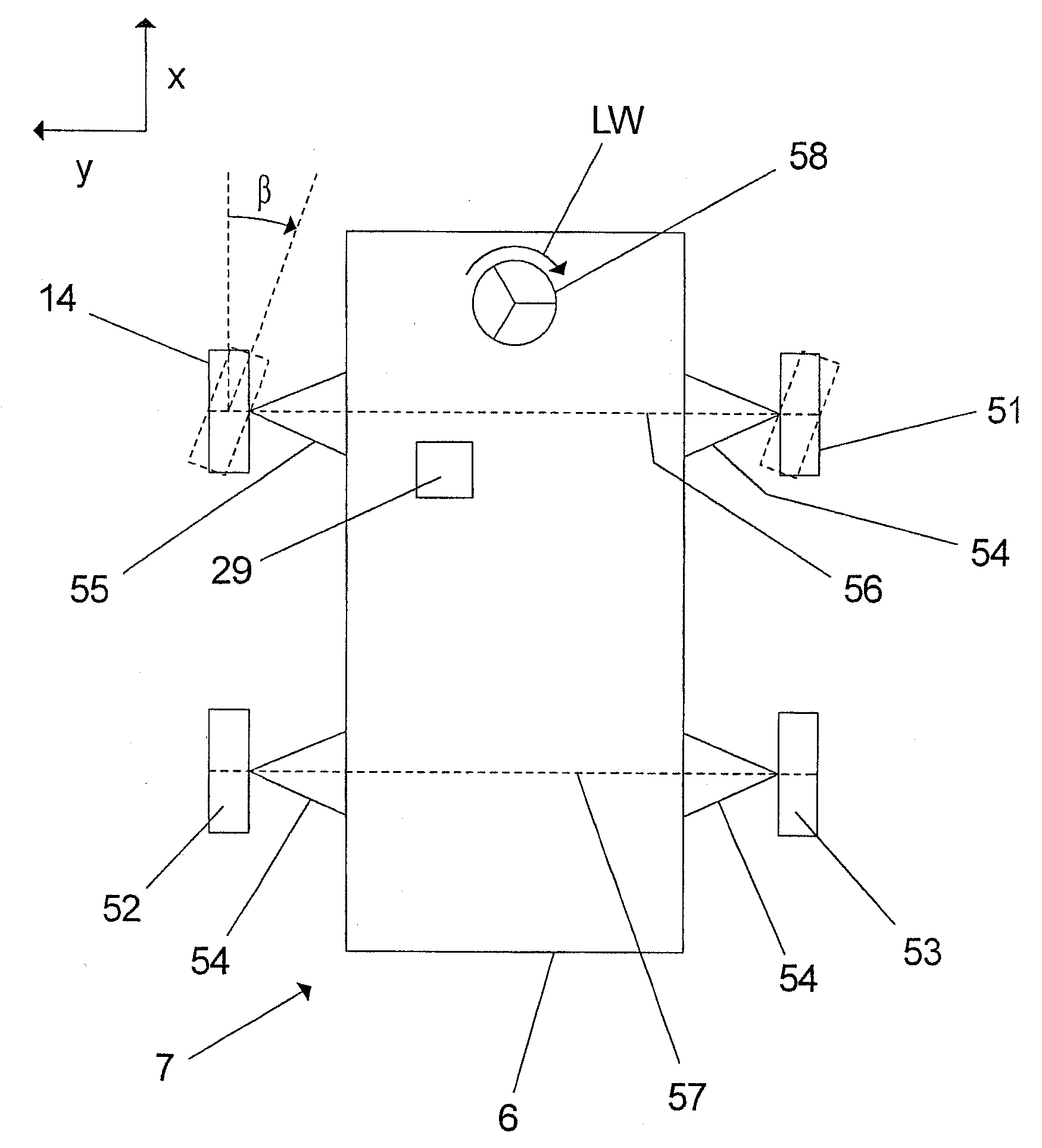
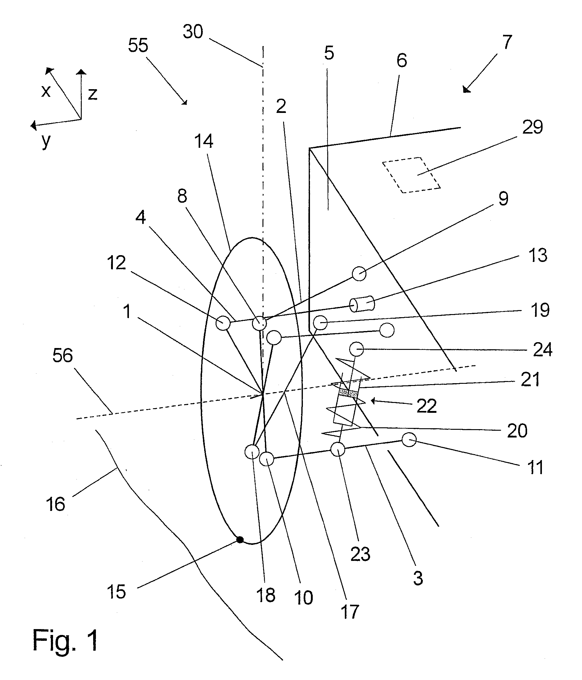
[0048]Referring to the drawings in particular, FIG. 1 shows a schematic view of a first embodiment of the wheel suspension 55 according to the present invention, wherein a wheel carrier 1 is connected via an upper suspension arm 2, a lower suspension arm 3 and a track rod 4 to a carrier element 5, which is part of a vehicle body 6 of a vehicle 7 shown partially. The upper suspension arm 2 is connected to the wheel carrier 1 via a ball and socket joint 8 and to the carrier element 5 via an elastomer bearing 9. The lower suspension arm 3 is connected to the wheel carrier 1 via a ball and socket joint 10 and to the carrier element 5 via an elastomer bearing 11. Furthermore, the track rod 4 is connected to the wheel carrier 1 via a ball and socket joint 12 and to the carrier element 5 via a steering gear 13 shown schematically, the track rod 4 being displaceable in its longitudinal direction by means of the steering gear 13. Such a displacement of the track rod 4 brings about a pivoting...


PUM


Abstract

Wheel suspension for a vehicle (7), with a carrier element (5), with a wheel carrier (1), which is arranged at a spaced location from the carrier element (5) and which is pivotable about a steering axle (30), with a wheel (14) mounted rotatably on the wheel carrier (1), with a steering wheel (58), which is mounted rotatably on the carrier element (5) at least indirectly and by means of which the wheel carrier (1) is pivotable about the steering axle (30), with at least one joint (8), which is connected to the wheel carrier (1) and which has a housing (26), a pivot pin (25) mounted pivotably in same and an angle-measuring device with a magnet (27) and with a magnetic field-sensitive sensor assembly unit (28), and with at least one guide means (2), via which the joint (8) is connected to the carrier element (5). A deflection (ω) of the pivot pin (25) relative to the housing (26) can be determined by means of the angle-measuring device in at least two different directions in space, and the magnetization (M) of the magnet (27) is oriented such that it extends at right angles to the steering axle (30).

Description

CROSS REFERENCE TO RELATED APPLICATIONS[0001]This application is a United States National Phase application of International Application PCT / DE 2006 / 001037 and claims the benefit of priority under 35 U.S.C. § 119 of DE 10 2005 028 501.5 filed Jun. 17, 2005, the entire contents of which are incorporated herein by reference.FIELD OF THE INVENTION[0002]The present invention pertains to a wheel suspension for a vehicle, with a carrier element, with a wheel carrier, which is arranged at a spaced location from the carrier element and is pivotable about a steering axle, with a wheel mounted rotatably at the wheel carrier, with a steering wheel, which is mounted rotatably at the carrier element at least indirectly and by means of which the wheel carrier is pivotable about the steering axle, with at least one joint, which is connected to the wheel carrier and which has a housing, a pivot pin mounted pivotably in same and an angle-measuring device with a magnet and with a magnetic field-sensi...

Claims


Application Information

Patent Timeline
Patent Type & Authority Applications(United States)
IPC IPC(8): B60G11/00
CPCB60G7/005B60G7/008B60G17/019B60G2200/144B60G2204/11B60G2204/148Y10T403/32631B60G2206/93B60G2206/99B60G2400/051B60G2401/172B62D15/021B62D15/023B60G2206/92G01D11/02B62D15/02B60G7/00
Inventor LOHMULLER, HOLGERHAEUSLER, FELIXKLANK, MICHAELSPRATTE, JOACHIM
Owner ZF FRIEDRICHSHAFEN AG
Why Eureka
Try Eureka