Wheel brake/drive force control device

a control device and brake technology, applied in the direction of brake systems, braking components, transportation and packaging, etc., can solve the problems of exceeding the braking-driving force or yaw moment required for the vehicle, and achieve the effect of reducing the travel stability of the vehicl

Active Publication Date: 2009-02-26
TOYOTA JIDOSHA KK
View PDF30 Cites 27 Cited by
  • Summary
  • Abstract
  • Description
  • Claims
  • Application Information

AI Technical Summary

Benefits of technology

[0008]Further, the above-described configuration reliably avoids the possibility that the target braking-driving forces of the wheels of the first and second wheel groups are calculated to assume values which cannot actually be generated by the wheels, or values smaller than the values which can actually be generated by the wheels. Thus, the above-described configuration enables the target braking-driving force and target yaw moment of the entire vehicle to be achieved to a possible extent through maximum utilization of the braking-driving forces of the individual wheels, and enables easy calculation of the target braking-driving forces of the individual wheels without requiring complex calculation such as convergence calculation, as will be described later in detail.
[0032]According to this configuration, at least one of the first and second adjustment means corrects the target braking-driving force or the target yaw moment to a value within an ellipse defined in an orthogonal coordinate system whose two axes correspond to the braking-driving force and yaw moment of the vehicle, the ellipse being located within ranges of the braking-driving force and yaw moment of the vehicle, which can be achieved by means of the braking-driving forces of the wheels, and having a center on the axis corresponding to the braking-driving force, and the directions of the major and minor radius of the ellipse coinciding with the axes of the orthogonal coordinate system. Therefore, even in a case where the target braking-driving force or the target yaw moment cannot be achieved by means of the braking-driving forces of the wheels of the first or second wheel group, a braking-driving force and a yaw moment close to the target braking-driving force and the target yaw moment can be achieved. In addition, even when the target braking-driving force and the target yaw moment change abruptly, the yaw moment and braking-driving force of the vehicle are prevented from changing abruptly, whereby the possibility that the travel stability of the vehicle lowers or an occupant of the vehicle feels an unnatural sensation can be effectively reduced.

Problems solved by technology

However, since there is a limit on the braking and driving force that each wheel can generate, in some cases, the braking-driving force or yaw moment required for the vehicle exceeds a level which can be attained through control of the braking-driving forces of the individual wheels.

Method used


Image

  • Wheel brake/drive force control device
  • Wheel brake/drive force control device
  • Wheel brake/drive force control device

Examples


first embodiment

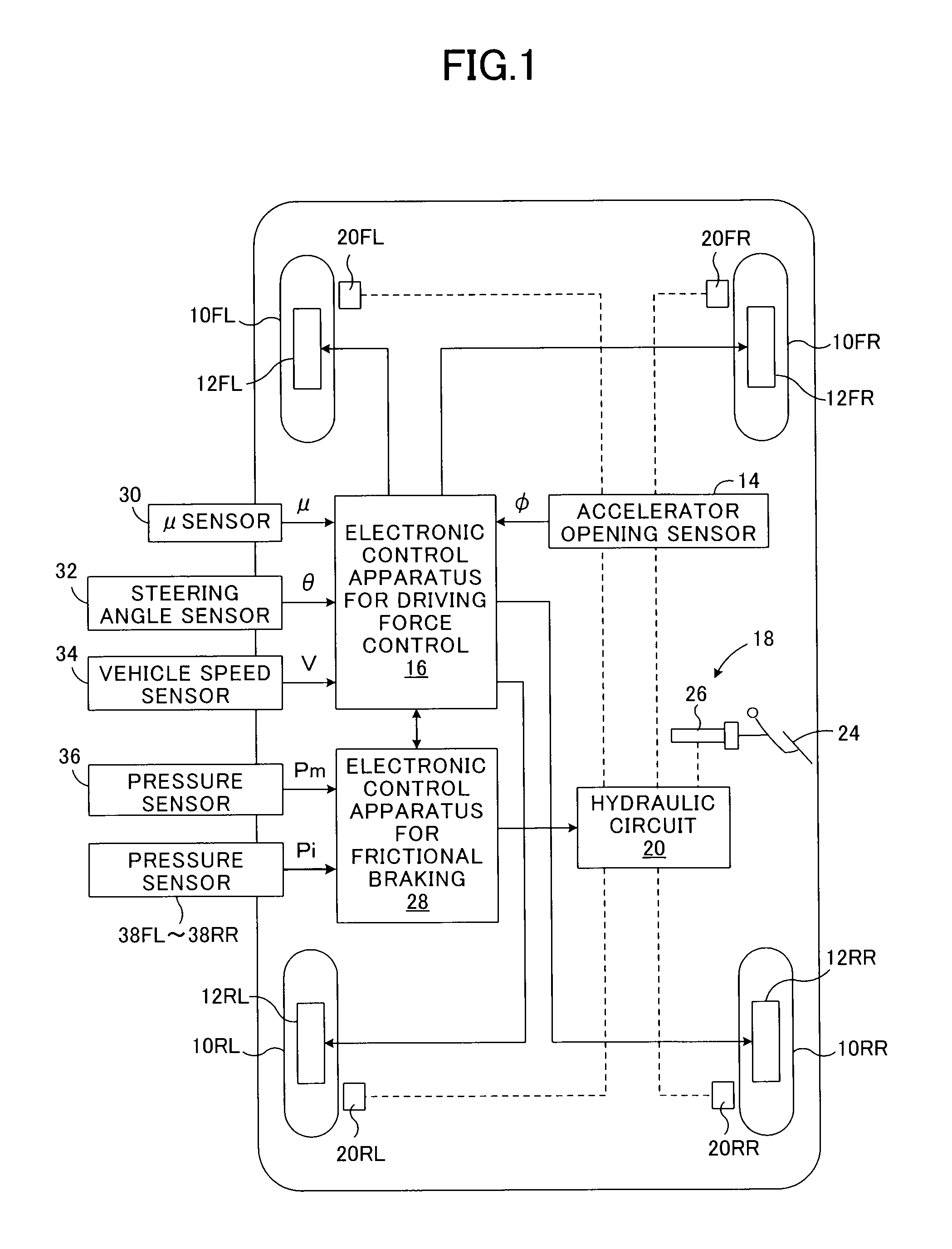
[0080]FIG. 1 is a schematic configurational view showing a first embodiment of a braking-driving-force control apparatus for a vehicle according to the present invention which is applied to a wheel-in-motor-type four-wheel-drive vehicle.

[0081]In FIG. 1, references numerals 10FL and 10FR respectively denote left and right front wheels, which are steerable wheels; and 10RL and 10RR respectively denote left and right rear wheels, which are non-steerable wheels. Motor generators 12FL and 12FR, each serving as an in-wheel motor, are built into the left and right front wheels 10FL and 10FR, and the left and right front wheels 10FL and 10FR are driven by the motor generators 12FL and 12FR. During braking, the motor generators 12FL and 12FR function as regenerative generators for the left and right front wheels, and generate regenerative braking forces.

[0082]Similarly, motor generators 12RL and 12RR, each serving as an in-wheel motor, are built into the left and right rear wheels 10RL and 1...

second embodiment

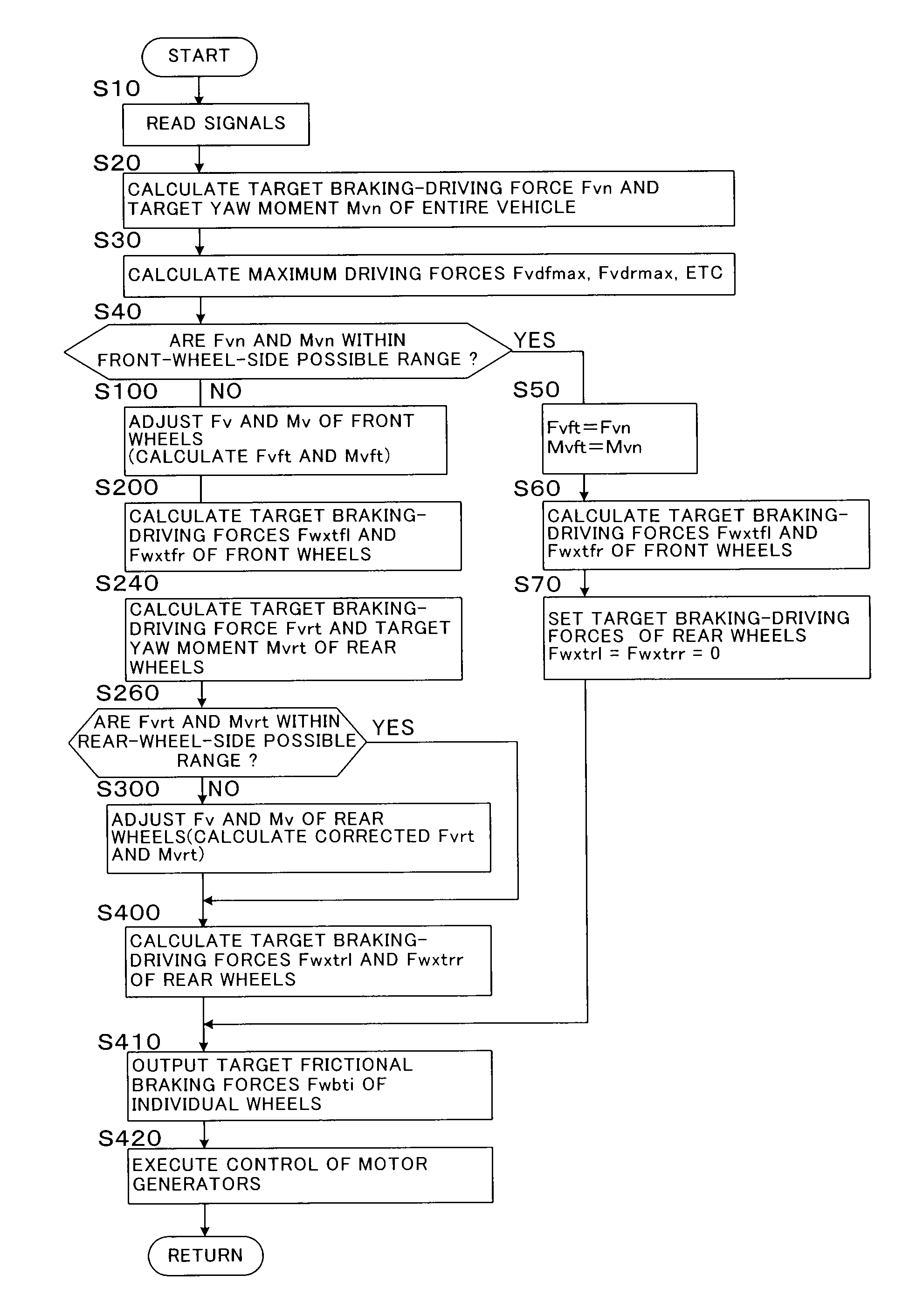
[0132]FIG. 5 is a flowchart showing a main portion of a braking-driving-force control routine in a second embodiment of the braking-driving-force control apparatus for a vehicle according to the present invention which is applied to a wheel-in-motor-type four-wheel-drive vehicle. In FIG. 5, steps identical to those shown in FIG. 4 are denoted by the same step numbers.

[0133]Although not shown in the drawings, in the second embodiment, the electronic control apparatus for driving force control 16 calculates a vehicle body speed Vb and acceleration slip amounts SAi (i=fl, fr, rl, rr) of the individual wheels from the wheel speeds Vwi of the individual wheels in a manner known in the art. When one of the acceleration slip amounts SAi becomes greater than a reference value for start of traction control (TRC control) and a condition for starting the traction control is satisfied, the electronic control apparatus for driving force control 16 performs the traction control by controlling the...

third embodiment

[0143]FIG. 7 is a flowchart showing a main portion of a braking-driving-force control routine in a third embodiment of the braking-driving-force control apparatus for a vehicle according to the present invention which is applied to a wheel-in-motor-type four-wheel-drive vehicle. In FIG. 7, steps identical to those shown in FIG. 4 are denoted by the same step numbers.

[0144]Although not shown in the drawings, in the third embodiment as well, the electronic control apparatus for driving force control 16 performs traction control when necessary; and the electronic control apparatus for braking force control 28 performs antiskid control when necessary.

[0145]In the third embodiment, steps 10 to 210, steps 260 to 400, and steps 410 and 420 are executed in the same manner as in the second embodiment. However, when an affirmative determination is made in step 210, that is, when the braking-driving force of at least one of the left and right front wheels is restricted because that wheel under...


PUM


Abstract

An object of the present invention is to achieve a braking-driving force and a yaw moment required for a vehicle to a possible extent within a range of braking-driving forces which the front and rear wheels can generate, when a target braking-driving force and a target yaw moment of the vehicle cannot be achieved by means of braking-driving forces that can be generated by the individual wheels. A target braking-driving force Fvn and a target yaw moment Mvn of the entire vehicle are calculated, and when the target braking-driving force Fvn and the target yaw moment Mvn cannot be achieved by means of the braking-driving forces of the front wheels, a target braking-driving force Fvft and a target yaw moment Mvft of the front wheels are adjusted such that the magnitudes of the braking-driving force and yaw moment of the vehicle produced by means of the braking-driving forces of the front wheels become the maximum at a ratio between Fvn and Mvn. A target braking-driving force Fvrt and a target yaw moment Mvrt of the rear wheels are calculated on the basis of Fvn, Mvn, Fvft, and Mvft, and similar adjustment is performed for them when necessarily.

Description

TECHNICAL FIELD[0001]The present invention relates to a braking-driving-force control apparatus for a vehicle, and more particularly, to a braking-driving-force control apparatus for a vehicle which controls the braking and driving forces of individual wheels.BACKGROUND ART[0002]As one type of a braking-driving-force control apparatus for a vehicle such as an automobile, there has conventionally known a driving force control apparatus which controls distribution of driving force to left and right wheels so as to impart a predetermined yaw moment to a vehicle, as described in, for example, Japanese Patent Application Laid-Open (kokai) No. H9-309357. Further, there has already been known a braking force control apparatus which controls the braking-driving force and yaw moment of a vehicle, through control of braking forces of individual wheels, so as to secure the traveling stability of the vehicle. When such a braking-driving-force control apparatus is employed, the traveling stabili...

Claims


Application Information

Patent Timeline
Patent Type & Authority Applications(United States)
IPC IPC(8): B60T8/62B60K17/348B60T8/1755B60W10/04B60W10/08B60W10/18B60W10/188B60W30/00B60W30/02
CPCB60L15/2036Y02T10/7275B60T2270/613B60W10/08B60W10/18B60W10/184B60W30/02B60W30/18127B60W40/11B60W40/112B60W40/114B60W2520/14B60W2520/30B60W2710/083B60W2720/30Y02T90/16B60T8/1755Y02T10/72Y02T10/64B60K17/348B60L15/20B60W10/04
Inventor MAEDA, YOSHINORIOSHIUMI, YASUHIROTSUCHIDA, MICHITAKAOKUMURA, KAZUYAYOSHIZUE, KENSUKEHOSOKAWA, AKIHIROSUGIYAMA, KOJI
Owner TOYOTA JIDOSHA KK
Why Eureka
Try Eureka