
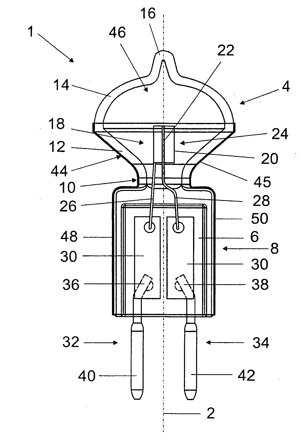
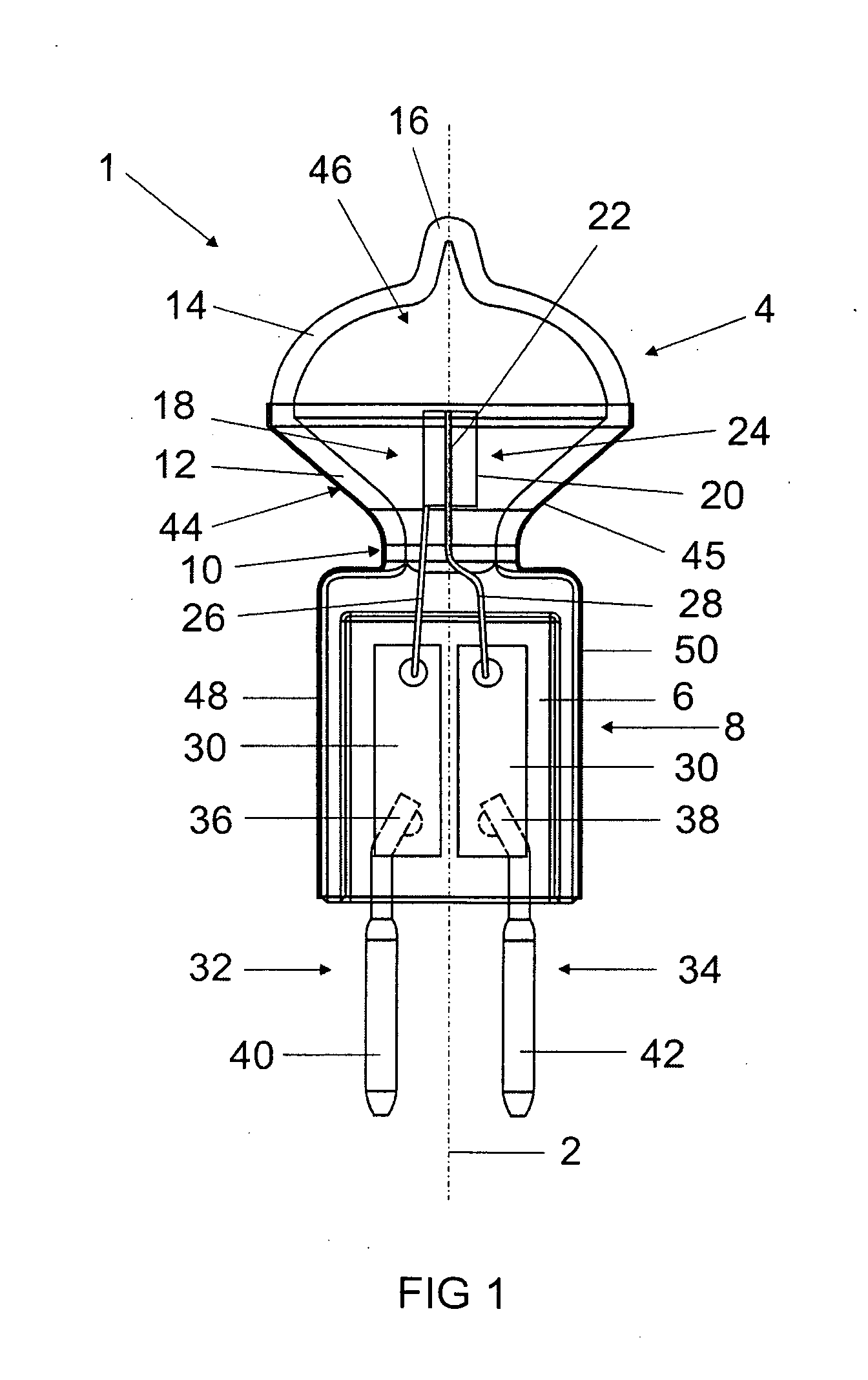
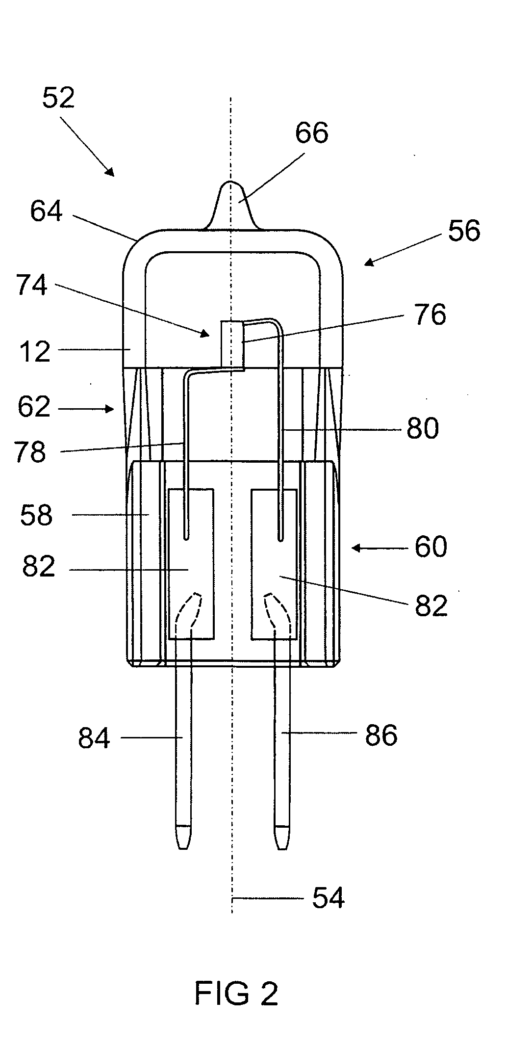
Reflector Lamp

a technology of reflector lamps and reflectors, which is applied in the direction of gas discharge lamps, incadescent envelopes/vessels, gas filling substances, etc., can solve the problems of thermally sensitive objects which the radiation from the reflector lamp may strike, the majority of radiant heat leaving the reflector lamp in the light exit direction, and the extremely compact design of the reflector lamp

Inactive Publication Date: 2009-02-26
OSRAM GMBH
View PDF3 Cites 3 Cited by
  • Summary
  • Abstract
  • Description
  • Claims
  • Application Information

AI Technical Summary

Benefits of technology

[0005]The invention is based on the object of providing a reflector lamp, in the case of which it is made possible for the transmission and reflection properties for light in the infrared wavelength range to be set in a defined manner with improved thermal stability and reflective effect of the reflective coating for light in the visible wavelength range in comparison with conventional solutions.

Problems solved by technology

As a result, such reflector lamps have an extremely compact design and require a minimum amount of installation space during fitting.
One disadvantage with such reflector lamps is firstly the fact that the transmission and reflection properties of the metallic specular layers are established over a wide spectral range, the metallic specular layer having a high reflectance for light in the visible wavelength range and also for light in the infrared wavelength range and, as a result, the majority of the radiant heat leaving the reflector lamp in the light exit direction.
As a result, thermally sensitive objects which the radiation from the lamp strikes may be damaged.
Furthermore, it is disadvantageous that such metallic specular layers in individual cases do not have sufficiently high thermal stability and, in particular in hot luminaires which are spatially restricted, vaporize over the lamp's life or diffuse into the glass of the lamp vessel.
As a result, the reflective effect of the reflective coating is decreased severely over the lamp's life.
Owing to the protective layers required, the coating process used for producing such reflector lamps is complex and cost-intensive.
It has also been shown that the reflectance values of the metallic reflective coatings consisting of aluminum or silver often do not meet the stringent requirements for the reflective effect.

Method used


Image

  • Reflector Lamp
  • Reflector Lamp
  • Reflector Lamp

Examples


Embodiment Construction

[0005]The invention is based on the object of providing a reflector lamp, in the case of which it is made possible for the transmission and reflection properties for light in the infrared wavelength range to be set in a defined manner with improved thermal stability and reflective effect of the reflective coating for light in the visible wavelength range in comparison with conventional solutions.

[0006]This object is achieved according to the invention by the features of claim 1. Particularly advantageous embodiments of the invention are described in the dependent claims.

[0007]The reflector lamp according to the invention has a light-transmitting lamp vessel, in which at least one luminous means is accommodated, a vessel section of the lamp vessel being provided with a reflective coating. According to the invention, the reflective coating has an interference filter (dichroitic filter), which is substantially impervious to light in the visible wavelength range and has defined transmis...


PUM


Abstract

A reflector lamp, in particular a halogen reflector lamp, has a light-transmitting lamp vessel, in which at least one luminous member is accommodated, at least one vessel section of the lamp vessel being provided with a reflective coating. According to the invention, the reflective coating has an interference filter, which is substantially impervious to light in the visible wavelength range and has defined transmission and reflection properties for light in the infrared wavelength range.

Description

TECHNICAL FIELD[0001]The invention relates to a reflector lamp in accordance with the precharacterizing clause of patent claim 1.PRIOR ART[0002]In principle, the reflector lamp according to the invention can be used in a large number of lamp systems. The main application area of the reflector lamp, however, should be in halogen reflector lamps for general lighting, for example for ceiling-mounted luminaires or recessed furniture luminaires, flexible light systems, signaling systems or radiators.[0003]Such a reflector lamp is known, for example, from DE 103 18 051 A1 by the Applicant. These conventional halogen reflector lamps have a light-transmitting lamp vessel which is sealed at one end and has an incandescent filament arranged therein. In comparison with a conventional reflector lamp, a vessel section of the lamp vessel is provided with a light-reflective coating in such halogen reflector lamps. The light-reflective coating in this solution is in the form of a metallic coating c...

Claims


Application Information

Patent Timeline
Patent Type & Authority Applications(United States)
IPC IPC(8): H01K1/32H01J61/35H01K7/02
CPCH01K1/325H01J61/35
Inventor BUNK, AXELBUNK, CHRISTAGLOCKLER, FRANKKRIEGLMEYER, CHRISTOPH
Owner OSRAM GMBH
Learn More