
Test system and daughter unit

a test system and daughter technology, applied in the field of test systems and daughter units, can solve the problems of difficult high frequency device testing accuracy of test apparatuses, inability to cut off electromagnetic noise incident from outside, so as to achieve the effect of cutting off noise from outsid

Active Publication Date: 2009-02-26
ADVANTEST CORP
View PDF7 Cites 19 Cited by
  • Summary
  • Abstract
  • Description
  • Claims
  • Application Information

AI Technical Summary

Benefits of technology

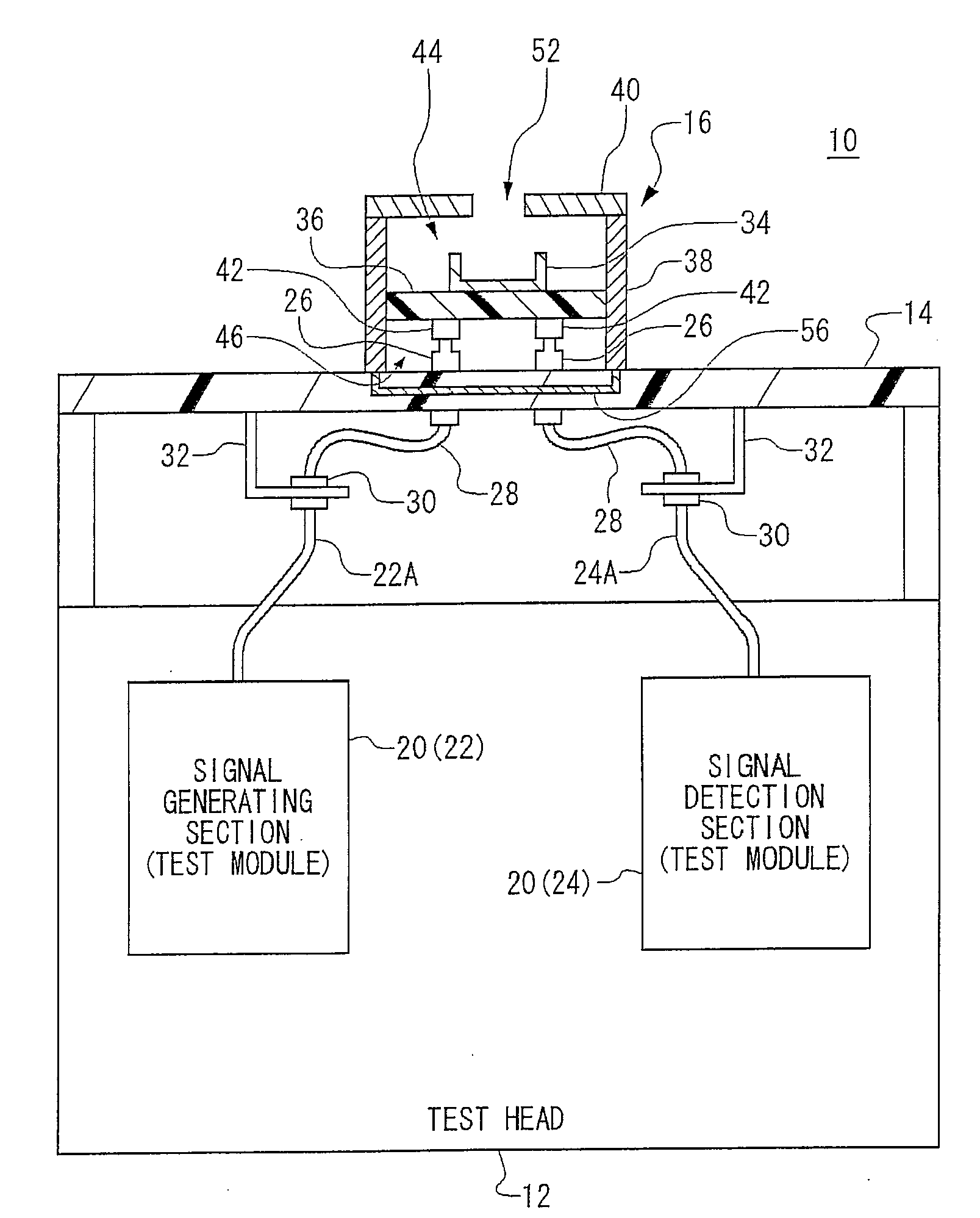
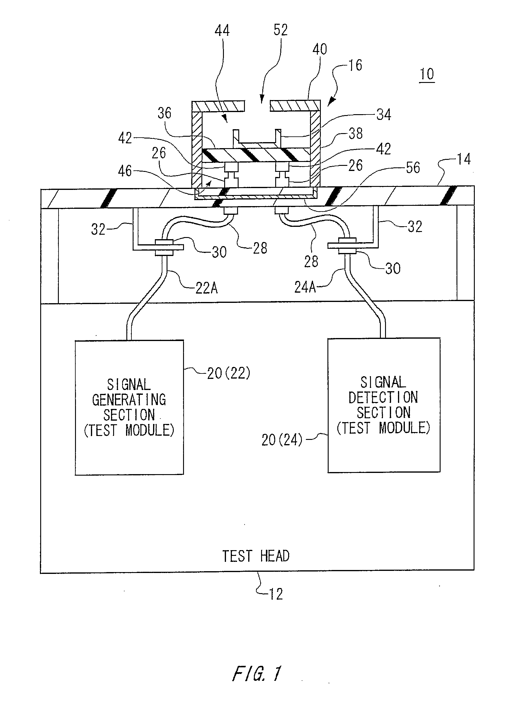
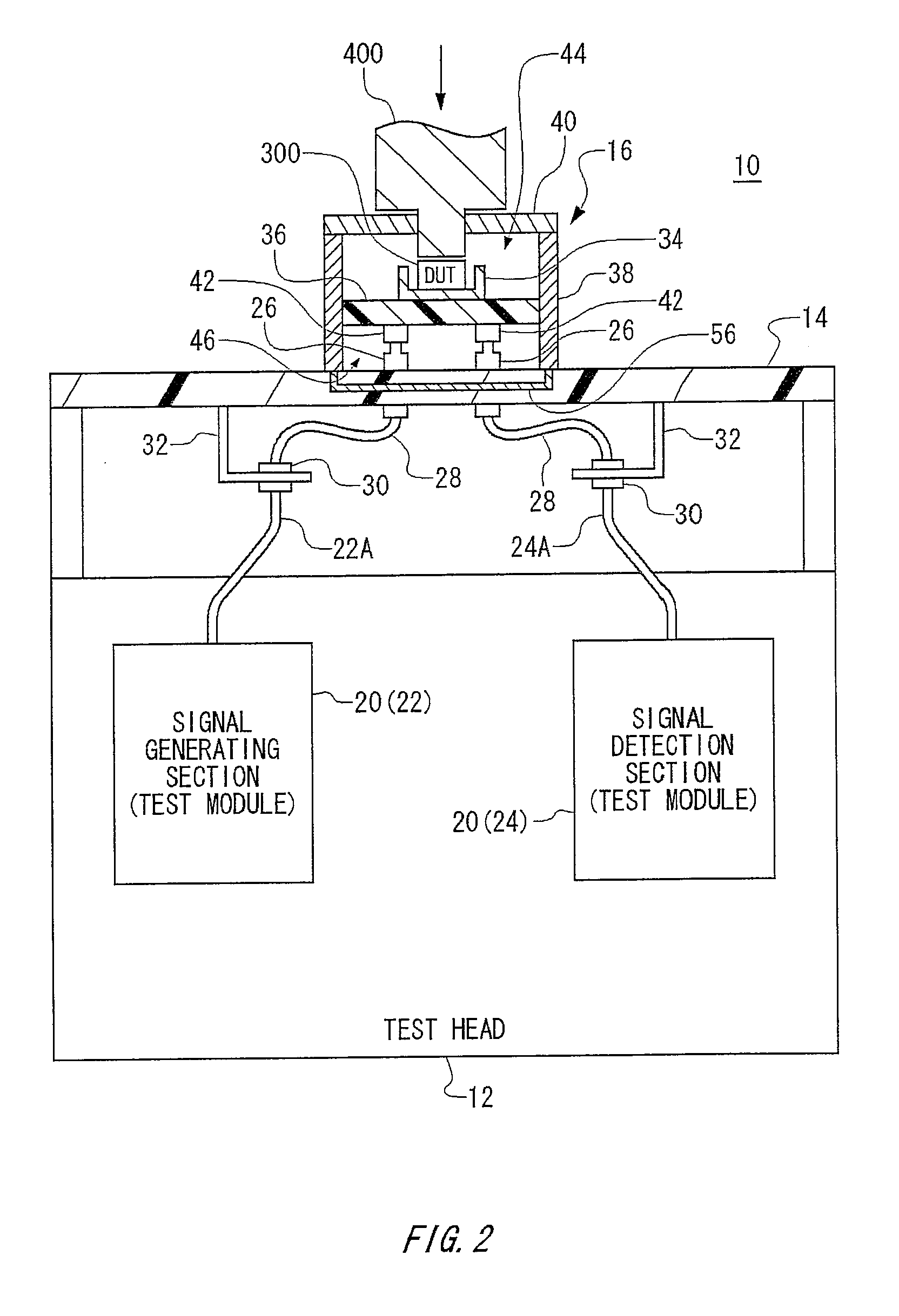
[0008]According to the first aspect related to the innovations herein, one exemplary test system is a test system that tests a device under test, the test system including: a test head that includes a test module that generates a test signal to be supplied to the device under test; a performance board that is mounted above the test head and conveys the test signal generated by the test module; and a daughter unit that is detachably mounted to the performance board, and conveys the test signal from the performance board to the device under test, where the daughter unit includes: a socket to which the device under test is mounted; a daughter board to which the socket is mounted; and an enclosure that accommodates therein the socket and the daughter board, and includes a daughter-unit shield that cuts off noise from outside with respect to the socket and the daughter board.

Problems solved by technology

In addition, such a test apparatus sometimes includes a relay board between the performance board and the device under test.
However, by using a performance board, it is not possible to cut off electromagnetic noise incident from outside.
Likewise, by using a relay board, it is not possible to cut off electromagnetic noise incident from outside.
As a result, it is difficult for a test apparatus to test a high frequency device with accuracy, by cutting off electromagnetic noise incident from outside.

Method used


Image

  • Test system and daughter unit
  • Test system and daughter unit
  • Test system and daughter unit

Examples


Embodiment Construction

[0023]Some aspects of the invention will now be described based on the embodiments, which do not intend to limit the scope of the present invention, but exemplify the invention. All of the features and the combinations thereof described in the embodiment are not necessarily essential to the invention.

[0024]FIG. 1 shows a configuration of a test system 10 according to the present embodiment to which a device 300 under test is not mounted. FIG. 2 shows a configuration of a test system 10 according to the present embodiment to which a device 300 under test is mounted.

[0025]A test system 10 tests a device 300 under test (DUT 300). The test system 10 may test a high frequency device for high-speed wireless communication as a device 300 under test. The test system 10 includes a test head 12, a performance board 14, and a daughter unit 16.

[0026]A test head 12 includes a test module 20 generating a test signal to be supplied to the device 300 under test. Furthermore, the teat head 12 may al...


PUM


Abstract

Provided is a test system that tests a device under test, the test system including: a test head that includes a test module that generates a test signal to be supplied to the device under test; a performance board that is mounted above the test head and conveys the test signal generated by the test module; and a daughter unit that is detachably mounted to the performance board, and conveys the test signal from the performance board to the device under test, where the daughter unit includes: a socket to which the device under test is mounted; a daughter board to which the socket is mounted; and an enclosure that accommodates therein the socket and the daughter board, and includes a daughter-unit shield that cuts off noise from outside with respect to the socket and the daughter board.

Description

BACKGROUND[0001]1. Technical Field[0002]The present invention relates to a test system and a daughter unit. In particular, the present invention relates to a test system and a daughter unit for testing a device under test.[0003]2. Related Art[0004]A test apparatus for testing a semiconductor and the like includes a test head including a test module outputting a test signal, and a performance board mounted above the test head. The performance board, to which the device under test is mounted, conveys a test signal outputted from the test module to the device under test.[0005]In addition, such a test apparatus sometimes includes a relay board between the performance board and the device under test. Such a test apparatus is able to mount semiconductors of a plurality of kinds to a common performance board.[0006]For example, when testing a high frequency device for use in high-speed wireless communication, it is desirable that a test apparatus performs the test by cutting off electromagn...

Claims


Application Information

Patent Timeline
IPC IPC(8): G01R31/02
CPCG01R1/18G01R31/2887G01R31/2839G01R31/2822
Inventor MIYAUCHI, KOUJIWATANABE, TOSHIYUKI
Owner ADVANTEST CORP
Learn More