Planar light unit and display apparatus having the same

a technology of display apparatus and light unit, which is applied in the direction of lighting and heating apparatus, instruments, lighting support devices, etc., can solve the problems of reducing the luminance at the light exiting surface of the lightguide plate, and affecting the efficiency of light entering

Inactive Publication Date: 2009-02-26
CITIZEN ELECTRONICS CO LTD
View PDF6 Cites 16 Cited by
  • Summary
  • Abstract
  • Description
  • Claims
  • Application Information

AI Technical Summary

Benefits of technology

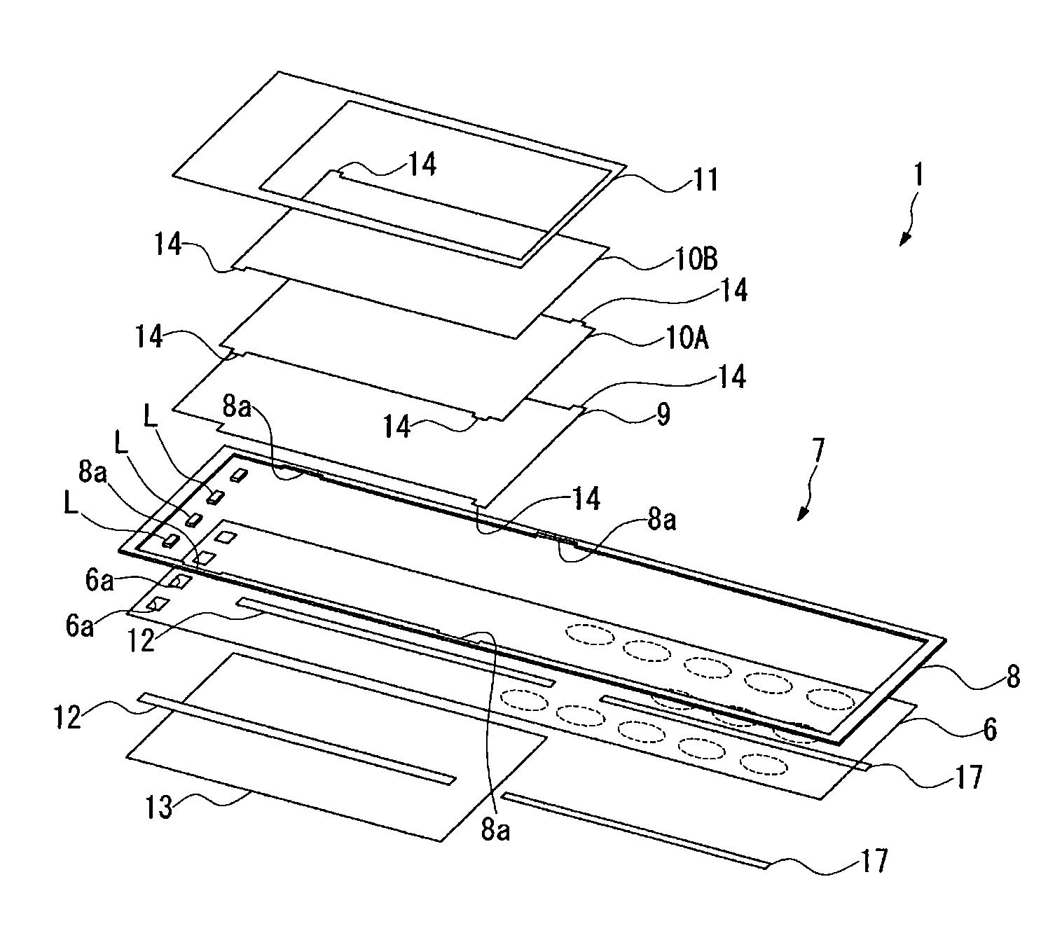
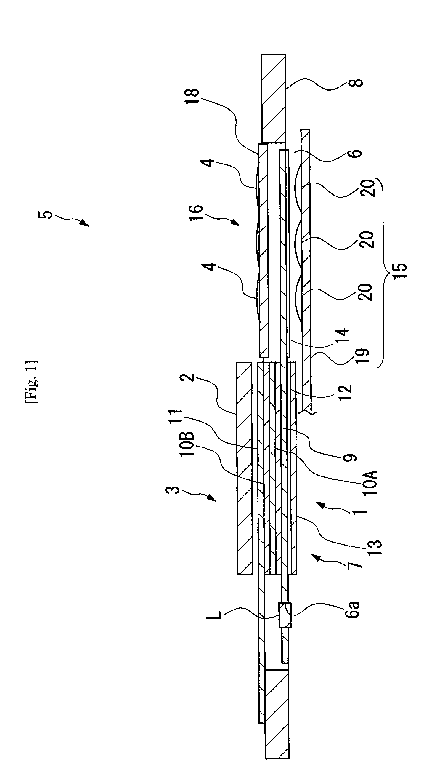
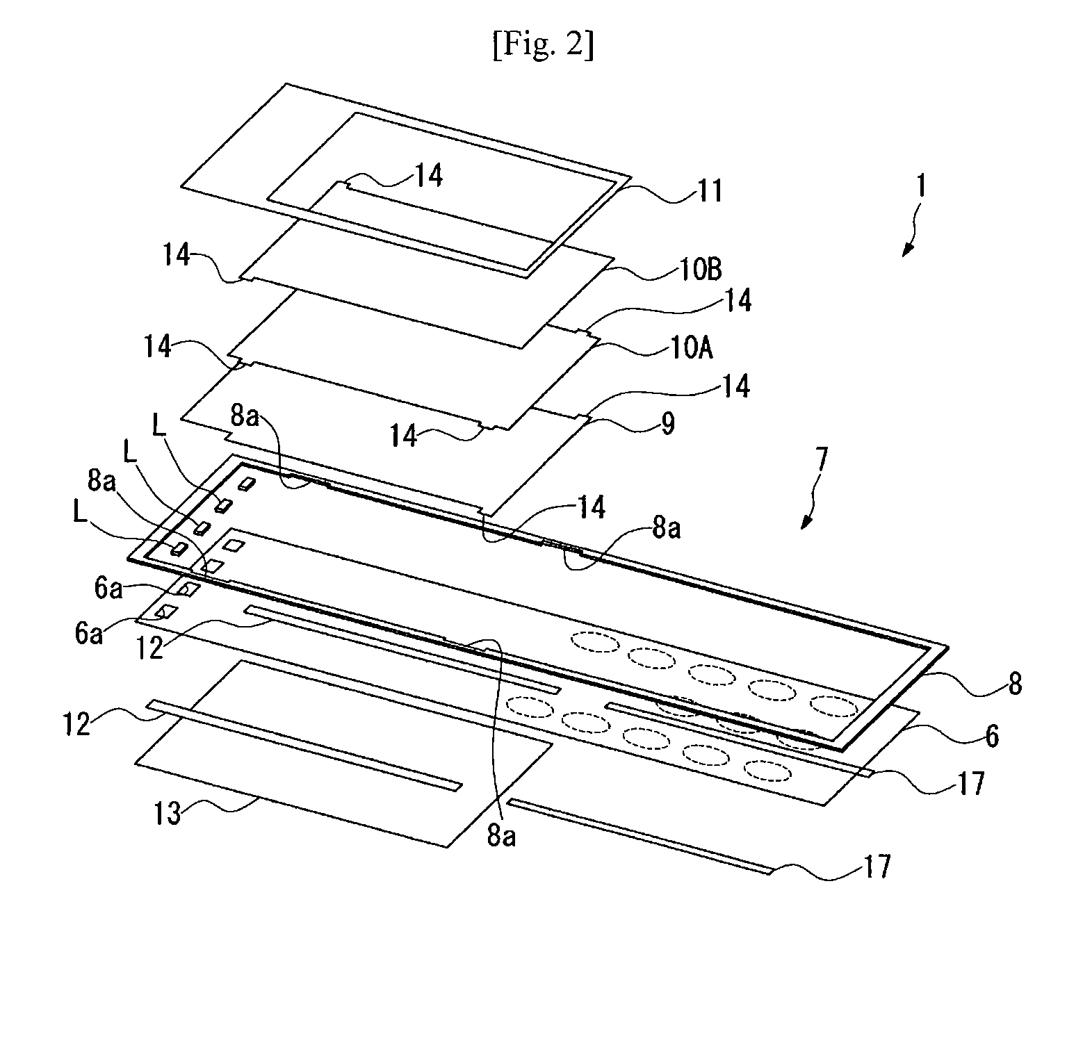
[0007]The present invention has been made in view of the above-described problems with the conventional art. Accordingly, an object of the present invention is to provide a planar light unit capable of preventing a misalignment between an LED light source and a film-shaped lightguide plate. Another object of the present invention is to provide a display apparatus having the planar light unit of the present invention.

Problems solved by technology

However, a misalignment between the LEDs and the lightguide plate is likely to occur.
If an error occurs in the positioning of the LEDs, the efficiency of light entering the lightguide plate degrades, resulting in a reduction in the luminance at the light exiting surface of the lightguide plate and a degradation of the luminance uniformity.
A backlight unit employing such a film-shaped lightguide plate also involves the above-described problem of the degradation of light entering efficiency caused by a misalignment between LEDs and the lightguide plate.

Method used


Image

  • Planar light unit and display apparatus having the same
  • Planar light unit and display apparatus having the same
  • Planar light unit and display apparatus having the same

Examples


seventh embodiment

[0064]In the seventh embodiment shown in FIG. 6, each light source accommodating hole 76a is in the shape of an elongated hole in which two LED light sources L can be disposed with a predetermined spacing therebetween, and has two retaining portions 76b formed in correspondence to the two LED light sources L.

[0065]In a case where one LED light source L is disposed in one light source accommodating hole 6a as in the first embodiment, the retaining portion 6b may not be sufficiently elastic. In such a case, it may be difficult to fit the LED light source L into the light source accommodating hole 6a. In the seventh embodiment, each light source accommodating hole 76a is in the shape of an elongated hole to dispose two LED light sources L therein. Consequently, the peripheral wall of the light source accommodating hole 76a is readily deflectable, as shown in part (a) of FIG. 7, and hence the light source accommodating hole 76a is easy to expand. Accordingly, the LED light sources L can...

eighth embodiment

[0067]Part (b) of FIG. 8 shows a modification of the In the modification, light source accommodating holes 86a are provided at both ends, respectively, of a film-shaped lightguide plate 86B, and four LED light sources L are disposed in each light source accommodating hole 86a. The LED light sources L disposed at one end of the film-shaped lightguide plate 86B may be used for the liquid crystal display panel 2, and the LED light sources L disposed at the other end of the film-shaped lightguide plate 86B may be used for the operation keys 4.

[0068]In the ninth embodiment shown in part (a) of FIG. 9, retaining portions 96b of a light source accommodating hole 96a are triangular in shape. Part (b) of FIG. 9 shows a modification of the ninth embodiment, in which retaining portions 106b of a light source accommodating hole 106a have a rectangular shape.

[0069]It should be noted that the present invention is not necessarily limited to the foregoing embodiments but can be modified in a varie...


PUM

PropertyMeasurementUnit
thicknessaaaaaaaaaa
wavelengthaaaaaaaaaa

Abstract

A backlight unit is capable of preventing an error in positioning of a light-emitting diode light source. The backlight unit (1) includes a film-shaped lightguide plate (6) having at least one light source accommodating hole (6a), and at least one light source (L) having at least one light-emitting diode element disposed in the light source accommodating hole. A retaining portion (6b) provided on the peripheral wall surface of the light source accommodating hole pressingly engages the peripheral wall surface of the light source to support it.

Description

RELATED APPLICATIONS[0001]This application claims priority under 35 U.S.C. §119 to Japanese Patent application No. JP2007-217676 filed on Aug. 23, 2007 and Japanese Patent application No. JP2008-151708 filed on Jun. 10, 2008, the entire contents of which are hereby incorporated by references.TECHNICAL FIELD[0002]The present invention relates to a planar light unit that illuminates a liquid crystal display panel or the like, and also relates to a display apparatus having the planar light unit.RELATED CONVENTIONAL ART[0003]Liquid crystal display apparatus for image display are widely used in displays of mobile phones, personal digital assistants (PDAs), mobile personal computers (PCs), automatic teller machines (ATMs), etc. These liquid crystal display apparatus employ a backlight unit that applies illuminating light to a light-transmitting liquid crystal display panel from the back thereof to enhance the luminance of the display screen on the front of the display panel.[0004]The back...

Claims


Application Information

Patent Timeline
Patent Type & Authority Applications(United States)
IPC IPC(8): F21V21/00F21V3/00G02F1/1333
CPCG02B6/0021G02B6/0073G02F1/133615G02B6/0091G02B6/0088
Inventor HORIUCHI, YOSHITAKEYAMADA, TATSURO
Owner CITIZEN ELECTRONICS CO LTD
Why Eureka
Try Eureka