Light source module of scanning device

a scanning device and light source technology, applied in the field of light source modules, can solve the problems of worse starting time and light-emitting efficiency of the conventional scanning device, and achieve the effects of shortening the starting time, prolonging the life time of the light source module, and improving the light-emitting efficiency

Inactive Publication Date: 2009-02-26
PRODISC TECH INC
View PDF1 Cites 73 Cited by
  • Summary
  • Abstract
  • Description
  • Claims
  • Application Information

AI Technical Summary

Benefits of technology

[0012]As mentioned above, the light source module of a scanning device according to the invention utilizes an LED disposed on the end portion or bottom surface of the light guide rod. The light emitted by the LED goes out uniformly via the light guide rod. In comparison with the prior art, the light source module of the invention does not only enhance the light-emitting efficiency but also shortens the starting time thereof Moreover, the life time of the light source module can be extended. Therefore, the overall scanning speed and quality of the scanning device are improved.

Problems solved by technology

However, using the CCFL as the light source 12, the starting time and light-emitting efficiency of the conventional scanning device 1 are worse than the scanning device using the light-emitting diode (LED) as the light source.

Method used


Image

  • Light source module of scanning device
  • Light source module of scanning device
  • Light source module of scanning device

Examples


first embodiment

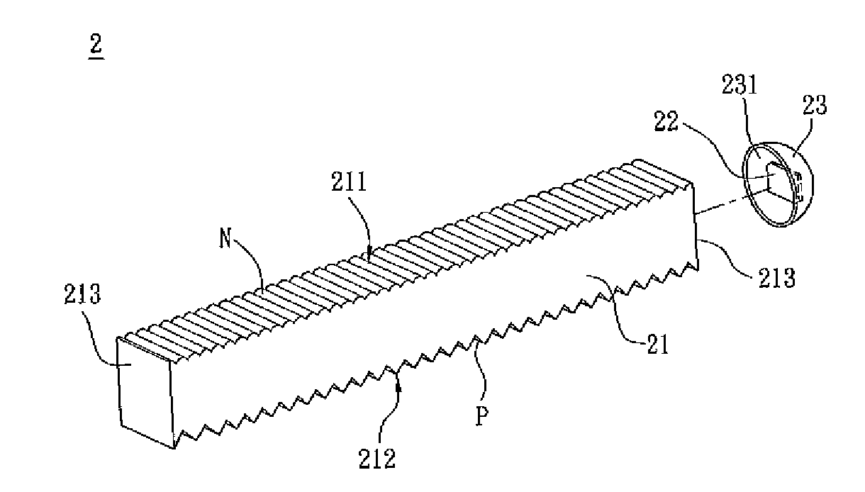
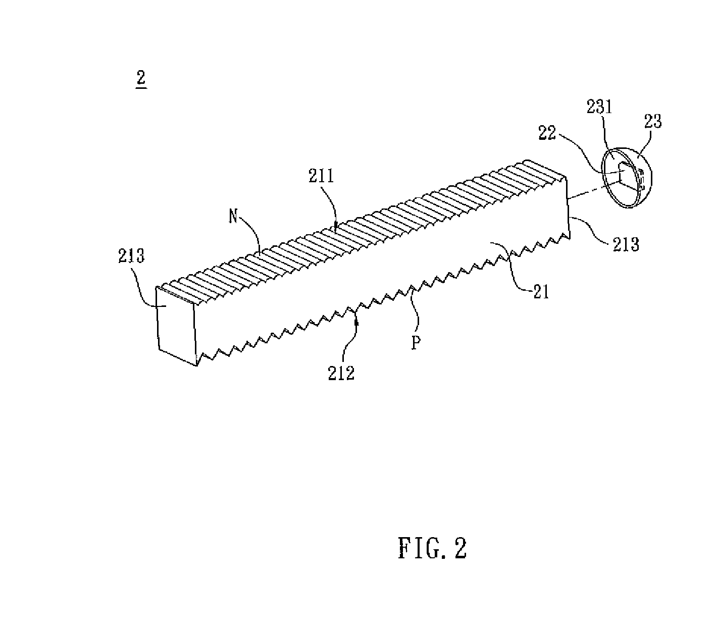
[0022]As shown in FIG. 2, a light source module 2 of a scanning device according to a first embodiment of the invention includes a light guide rod 21 and an LED 22. The light guide rod 21 has a top surface 211, a bottom surface 212 and two end portions 213. The light guide rod 21 can be a rectangular or wedge light guide rod with a flat bottom surface or a rectangular light guide rod with a curved bottom surface. In this embodiment, the light guide rod 21 is a rectangular light guide rod. The top surface 211 and the bottom surface 212 are disposed opposite to each other. The top surface 211 is a light-emitting surface, and the bottom surface 212 is a reflective surface. In this embodiment, the top surface 211 has several lenticular lenses N disposed in parallel. The bottom surface 212 has several prisms, at least one Fresnel lens or several mesh points. This embodiment preferably has several prisms P disposed in parallel on the bottom surface 212.

[0023]The LED 22 is an LED device or...

second embodiment

[0026]As shown in FIG. 4, a light source module 3 of a scanning device according to a second embodiment of the invention includes a light guide rod 31, two LED's 32 and two reflective elements 33. The basic structure and functions of the light guide rod 31 are the same as those of the light guide rod 21 in the first embodiment, so the descriptions thereof will be omitted. The difference between this embodiment and the first embodiment is in that the light source module 3 has two LED's 32 and two reflective elements 33 disposed respectively on the two end portions 313 of the light guide rod 31 for enhancing the brightness of the light source module 3

third embodiment

[0027]As shown in FIG. 5, a light source module 4 of a scanning device according to a third embodiment of the invention includes a light guide rod 41 and a LED 42. The structures and functions of the light guide rod 41 and the LED 42 are the same as those of the light guide rod 21 and the LED 22 in the first embodiment, so the detailed descriptions thereof will be omitted. The difference between this embodiment and the first embodiment is that, in addition to a molding 421, the LED 42 of the light source module 4 has a light guide lens 43 covering thereon. The light guide lens 43 can modify the optical shape of the light emitted by the LED 42 and enhance the light usage thereof.

[0028]To be noted, the LED 42 can be disposed concurrently on the two end portions 413 of the light guide rod 41.


PUM


Abstract

A light source module of scanning device includes a light guide rod and a light emitting diode. The light guide rod has a top surface, a bottom surface and two end portions. The top surface and the bottom surface are disposed opposite to each other. The light emitting diode is disposed adjacent to one of the end portions.

Description

CROSS REFERENCE TO RELATED APPLICATIONS[0001]This Non-provisional application claims priority under 35 U.S.C. §119(a) on Patent Application No(s). 096131285 filed in Taiwan, Republic of China on Aug. 23, 2007, the entire contents of which are hereby incorporated by reference.BACKGROUND OF THE INVENTION[0002]1. Field of Invention[0003]The invention relates to a light source module and, in particular, to a light source module of a scanning device.[0004]2. Related Art[0005]Data image inputs of modern scanners, fax machines, copy machines, or multi-function peripherals require the use of light sources during the scanning process. Therefore, the light-emitting efficiency, stability, and starting time of the light source are closely related to the overall quality and performance of the scanning device.[0006]As shown in FIG. 1, a conventional scanning device 1, which is a scanner, includes an image sensor 11, a light source 12 and a transparent supporting plate 13. The image sensor 11 can ...

Claims


Application Information

Patent Timeline
Patent Type & Authority Applications(United States)
IPC IPC(8): F21V7/04
CPCG02B6/001G02B6/0038H04N1/1017H04N1/0284G02B6/0061
Inventor CHEN, CHING-CHUNGCHOU, YEN-CHUN
Owner PRODISC TECH INC
Why Eureka
Try Eureka