Method of seismic data processing

Inactive Publication Date: 2009-02-26
CGGVERITAS SERVICES
View PDF8 Cites 13 Cited by
  • Summary
  • Abstract
  • Description
  • Claims
  • Application Information

AI Technical Summary

Benefits of technology

[0009]An objective of the invention is to improve the quality of the proce

Problems solved by technology

The estimation of the time- or depth-velocity model is an important and difficult step in the seismic processing chain.
However, while precise analyses have been carried out in the case of the depth migration, they

Method used


Image

  • Method of seismic data processing
  • Method of seismic data processing
  • Method of seismic data processing

Examples


Embodiment Construction

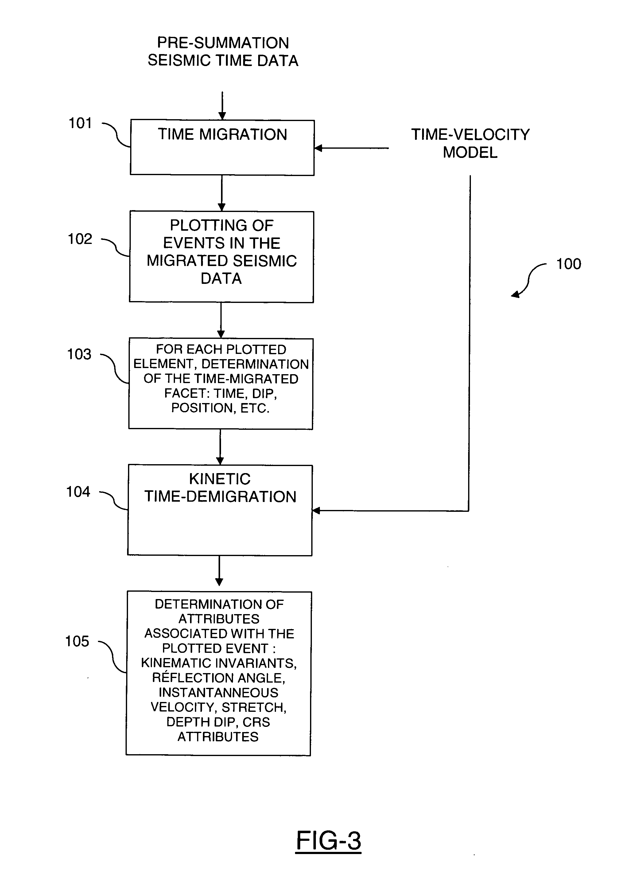
[0046]The seismic data processing process shown in FIGS. 3 and 4 includes two main processing phases: a first phase 100 of constituting kinematic invariants (FIG. 3) and a second phase 200 of tomographic inversion of these kinematic invariants, i.e. an estimation of the time- or depth-velocity model (FIG. 4), on the basis of the kinematic invariants.

Determination of the Kinematic Invariants

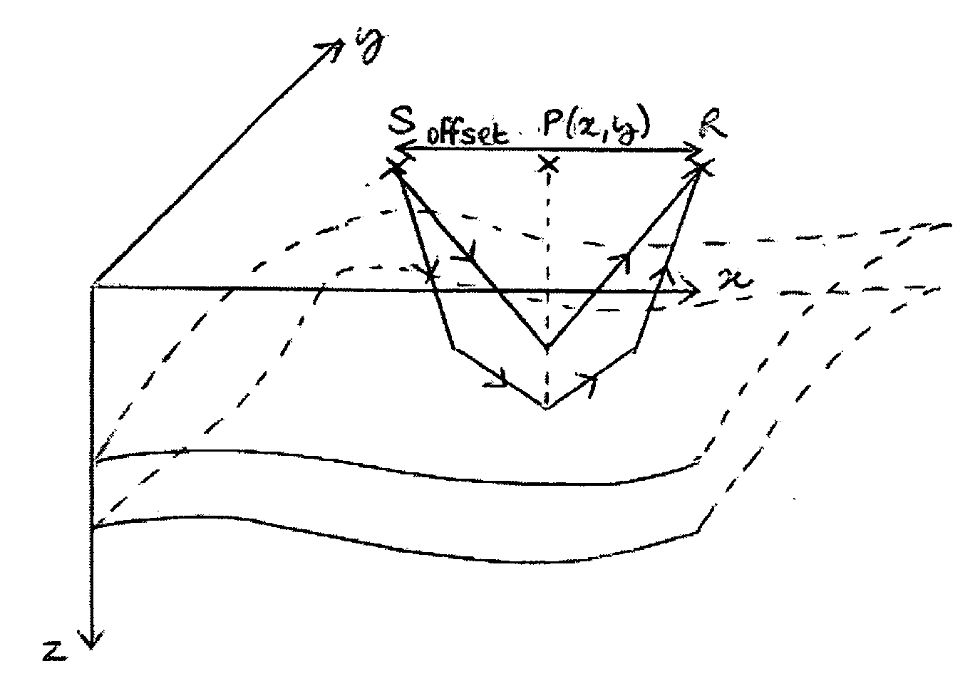
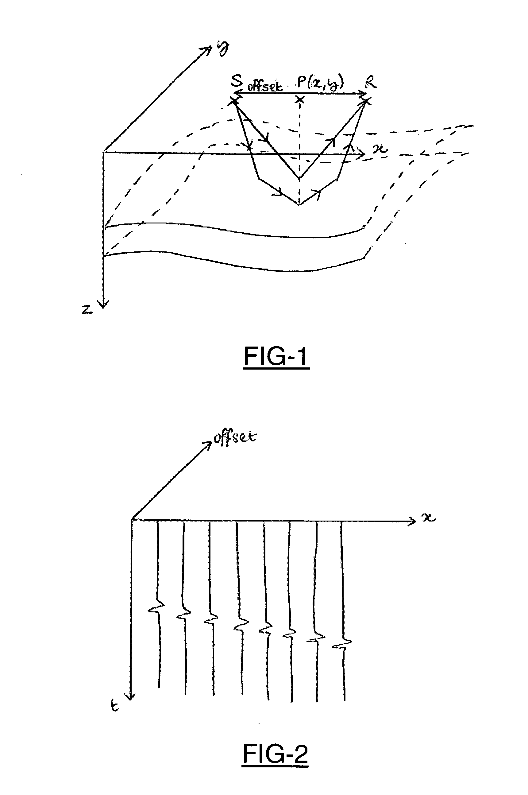
[0047]The first phase of the processing process shown in FIG. 3 is applied to time traces before migration. These traces correspond to the recording, as a function of time, by a sensor, of the amplitude of the signal propagated underground.

[0048]According to a first step 101, a migration of these seismic traces is performed according to an initial time-velocity model (PreSTM).

[0049]According to a second step 102, on each gather of traces obtained in the previous step, one or more events reflected in line with the surface point considered are picked.

[0050]FIG. 5 diagrammatically shows a cross-secti...


PUM


Abstract

The invention relates to a method of seismic data processing, wherein the data includes a set of seismic traces, with each trace including a signal that has been recorded by a sensor after having been propagated in a subsurface area, with the signal being defined by an amplitude as a function of time, including the steps of:
    • migration of data according to an initial time-velocity model,
    • picking in the time-migrated data one or more event(s) corresponding to one or more subsurface reflector(s) so as to obtain facets locally approximating the event,
    • kinematic demigration of the facets plotted so as to obtain simplified seismic data in the form of a set of facets and a set of attributes associated with the facets.

Description

FIELD OF THE INVENTION[0001]This invention relates to the field of seismic imaging. It relates more specifically to a method of seismic data processing.PRIOR ART[0002]In order to produce images of the subsurface, geologists or geophysicists conventionally use acoustic transmitters placed, for example, at the surface. As shown in FIG. 1, the transmitters S (also called sources) transmit waves that are propagated in the subsurface and reflected on the surfaces of the layers thereof (reflectors). The acoustic waves reflected toward the surface are recorded as a function of time by receivers R. The signals recorded by the receivers are called seismic traces.[0003]Various digital processing techniques are conventionally applied to these traces so as to improve the signal-to-noise ratio and facilitate their interpretation. These techniques include the migration operation, which consists of determining, for a plurality of surface positions P of coordinates (x, y), a collection of migrated ...

Claims


Application Information

Patent Timeline
IPC IPC(8): G01V1/28
CPCG01V1/28G01V1/00G01V2210/51G01V1/307G01V1/301
Inventor HERRMANN, PHILIPPELAMBARE, GILLESGUILLAUME, PATRICESUAUDEAU, ERIC
Owner CGGVERITAS SERVICES
Why Eureka
Try Eureka