Dental drill

a dental drill and drill bit technology, applied in dentistry, dental tools, medical science, etc., can solve the problems of increasing the cost of different dental drills, requiring a considerable time for exchanging dental, and affecting the quality of the surface to be processed, so as to achieve the effect of reducing the vibration of the dental drill, and reducing the cost of dental replacemen

Inactive Publication Date: 2009-02-26
GEBR BRASSELER GMBH & CO KG
View PDF3 Cites 24 Cited by
  • Summary
  • Abstract
  • Description
  • Claims
  • Application Information

AI Technical Summary

Benefits of technology

[0008]According to the invention, the cross-cut is formed in the shape of a groove interrupting the cutting edge and therewith the cutting flange. Therefrom, there results an increased cutting efficiency. The chips of the removed material are divided into small chips.
[0009]The smooth cutting edges of the distal end portion of the head as well as the of the end portion of the head facing the shaft enable a high-quality preparation with very good surfaces.
[0011]The dentist therewith can perform different processing steps with different qualities by using one single dental drill, without the necessity to exchange the tool. Therefrom, there results a considerable time saving.
[0012]The quality of the surface to be processed is also enhanced by the respective end portions of the head which has no cross-cuts in that only a minimum vibration of the dental drill occurs during operation.

Problems solved by technology

Such cutting edges being provided with cross-cuts, however, result in an inferior surface quality, such that these dental drills may only be used in a first processing step for a rough pre-processing.
This results in increased costs for the different dental drills and requires a considerable expenditure of time for exchanging the dental drills during the preparation treatment.

Method used


Image

  • Dental drill
  • Dental drill
  • Dental drill

Examples


Embodiment Construction

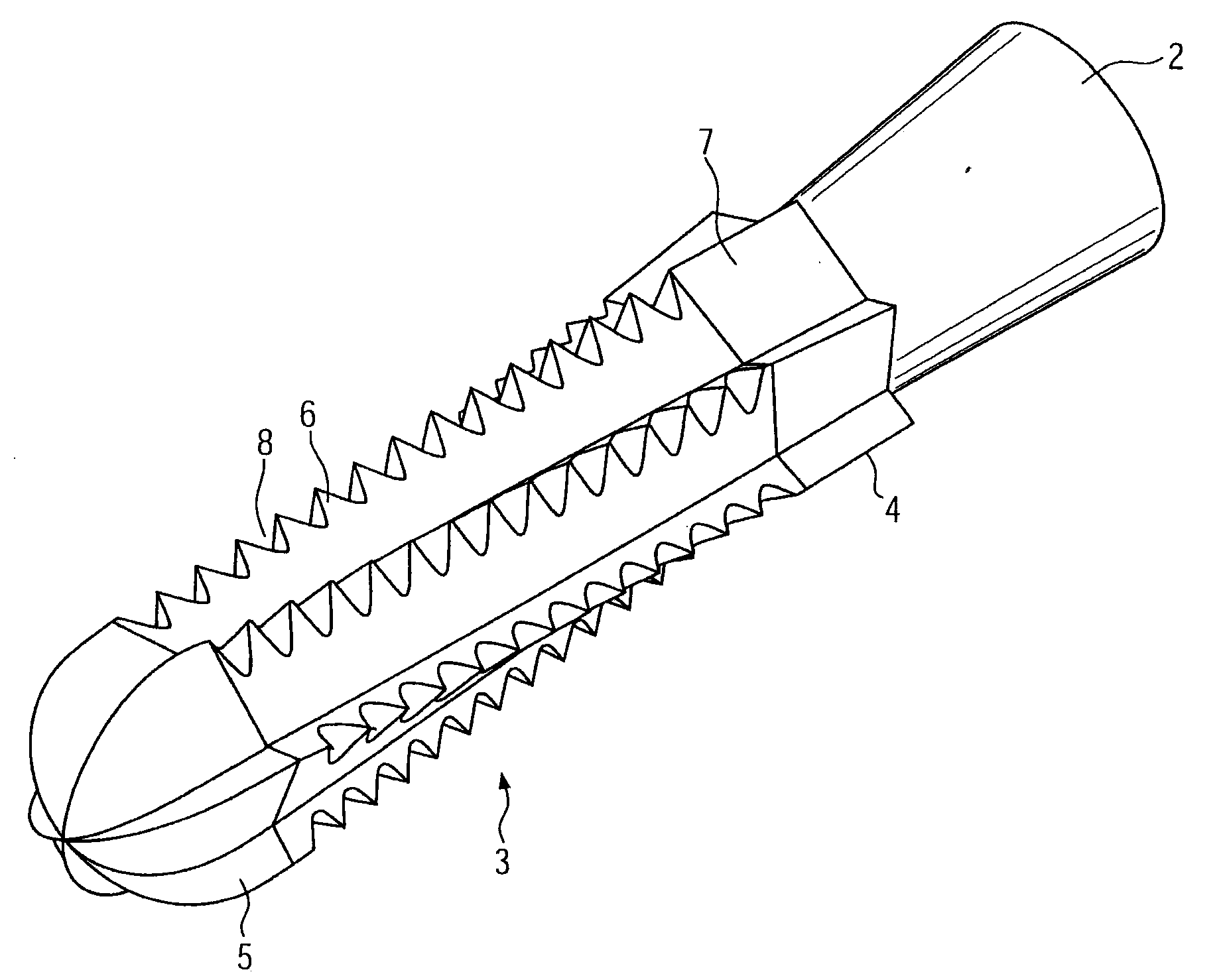
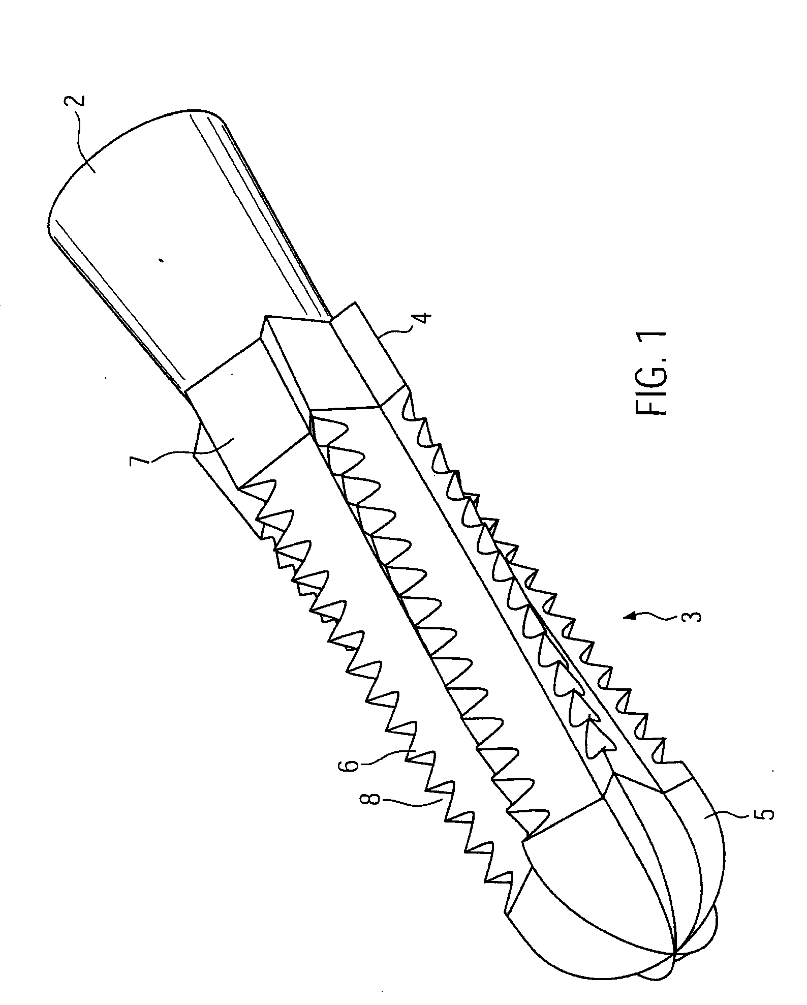
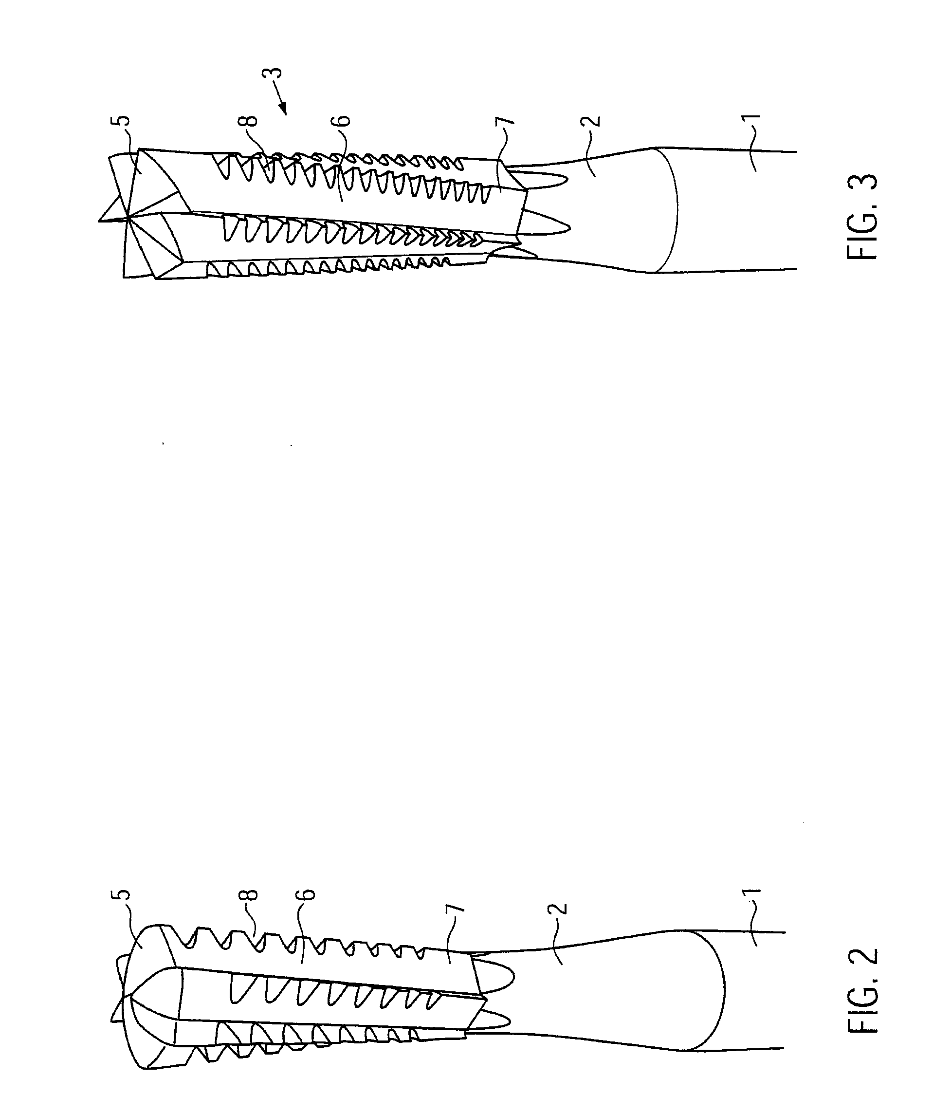
[0021]FIGS. 1 and 4 show a first preferred embodiment of an inventive dental drill comprising a cylindrical shaft 1 which is provides with clamping means (not shown) in order to be insertable into a driving tool and coupled therewith. The shaft comprises a tapering shaft end 2 which is integrally provided with a head 3. The head 3 is substantially shaped cylindrical and provided with cutting edges 4 which are formed substantially straight-lined and have a twist.

[0022]The head 3 is divided into three portions, i. e. a distal end portion 5, a middle portion 6 as well as an end portion 7 adjacent to the shaft end 2.

[0023]As is discernible from FIGS. 1 and 4, the distal end portion 5 of the head 3 is formed semi-spherical. The cutting edges converge toward the center as it is discernible from the front view of FIG. 9. FIG. 8 shows a technical drawing analogous to the view of FIG. 4.

[0024]The distal end portion 5 of the head 3 has cutting edges which are formed continuously and therewith...


PUM


Abstract

The invention relates to a dental drill comprising a shaft as well as a head being provided with a plurality of cutting edges extending lengthwise of the head, wherein the cutting edges are provided with at least one cross-cut at a middle portion of the head.

Description

FIELD OF THE INVENTION[0001]The present invention relates to a dental drill having a shaft, the distal free end of which is provided with a head provided comprising cutting edges.BACKGROUND OF THE INVENTION[0002]From the state of the art, it is known to manufacture dental drills with different designs. The shape as well as the type of the cutting edges (toothing) are adapted to the respective purposes of application, such that the dentist may select the optimum tool for each preparation step.[0003]The design of the cutting edges may be straight-lined. However, it is also known to provide the complete cutting edges of the head with one or more cross-cuts. These cross-cuts, having the shape of peripheral grooves or helical grooves, divide the cutting edges into individual cutting portions. Therewith, small chips are produced. Furthermore, the cutting efficiency of the dental drill is increased.[0004]Such cutting edges being provided with cross-cuts, however, result in an inferior surf...

Claims


Application Information

Patent Timeline
Patent Type & Authority Applications(United States)
IPC IPC(8): A61C5/02
CPCA61C3/02
Inventor DANGER, KARL-HEINZ
Owner GEBR BRASSELER GMBH & CO KG
Why Eureka
Try Eureka