
Transmitter and Transmission Method Thereof

a transmission method and transmitter technology, applied in the direction of digital transmission, electric long antennas, antennas, etc., can solve the problems of increasing the bandwidth and energy of the output, reducing the efficiency of the transmission method, and so as to achieve the effect of reducing the out-of-band energy of the output signal

Active Publication Date: 2009-02-26
REALTEK SEMICON CORP
View PDF6 Cites 9 Cited by
  • Summary
  • Abstract
  • Description
  • Claims
  • Application Information

AI Technical Summary

Benefits of technology

[0009]Therefore, the object of this invention is to provide a transmitter for wireless communication and a transmission method thereof, in which an out-of-band energy of an output signal is reduced while maintaining the energy level of the output signal that is within the desired frequency band.

Problems solved by technology

This problem is exacerbated by increases in the bandwidth and energy of the output 10 signal.
However, if the energy of the output signal is increased to enlarge the range of coverage, or if the bandwidth of the output signal is increased to increase transmission data capacity, the energy of the output signal outside the predetermined frequency band (i.e., out-of-band energy of the output signal) becomes excessive, such that interference occurs with other wireless communication systems using different frequency bands.

Method used


Image

  • Transmitter and Transmission Method Thereof
  • Transmitter and Transmission Method Thereof
  • Transmitter and Transmission Method Thereof

Examples


Embodiment Construction

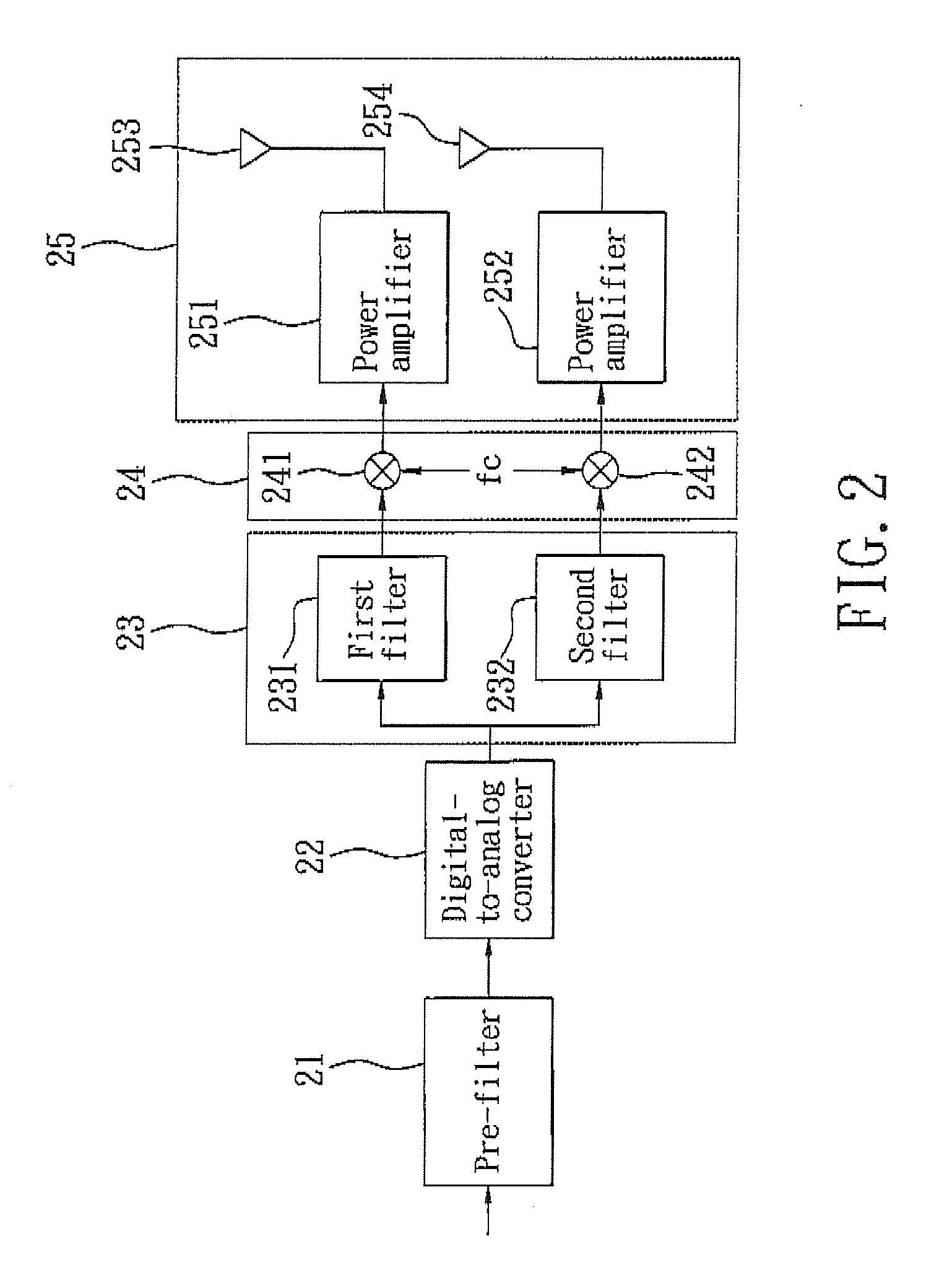
[0020]Referring to FIG. 2, a transmitter according to a first embodiment of the present invention operates in a predetermined frequency band. The transmitter includes a pre-filter 21, a digital-to-analog (D / A) converter 22 coupled to the pre-filter 21, a bandwidth-converting unit 23 coupled to the D / A converter 22, a mixing unit 24 coupled to the bandwidth-converting unit 23, and a transmitting unit 25 coupled to the mixing unit 24. In the first embodiment, the bandwidth-converting unit 23 includes a first filter 231 and a second filter 232, the mixing unit 24 includes two mixers 241, 242, and the transmitting unit 25 includes two power amplifiers 251, 252 and two antennas 253, 254.

[0021]As shown in FIG. 2, an input signal is filtered through the pre-filter 21 to obtain a filtered signal. Subsequently, the D / A converter 22 performs D / A conversion of the filtered signal to obtain an analog signal having a predetermined bandwidth.

[0022]Accordingly, the first filter 231 and the second ...


PUM


Abstract

A signal transmission method includes: converting an input signal to generate a first converted signal having a first bandwidth, and a second converted signal having a second bandwidth; mixing the first converted signal with an oscillation signal to generate a first mixed signal, and mixing the second converted signal with the oscillation signal to generate a second mixed signal; and transmitting the first and second mixed signals by different antennas; wherein the input signal has a predetermined bandwidth, the first bandwidth is smaller than the predetermined bandwidth; and the second bandwidth is smaller than the predetermined bandwidth.

Description

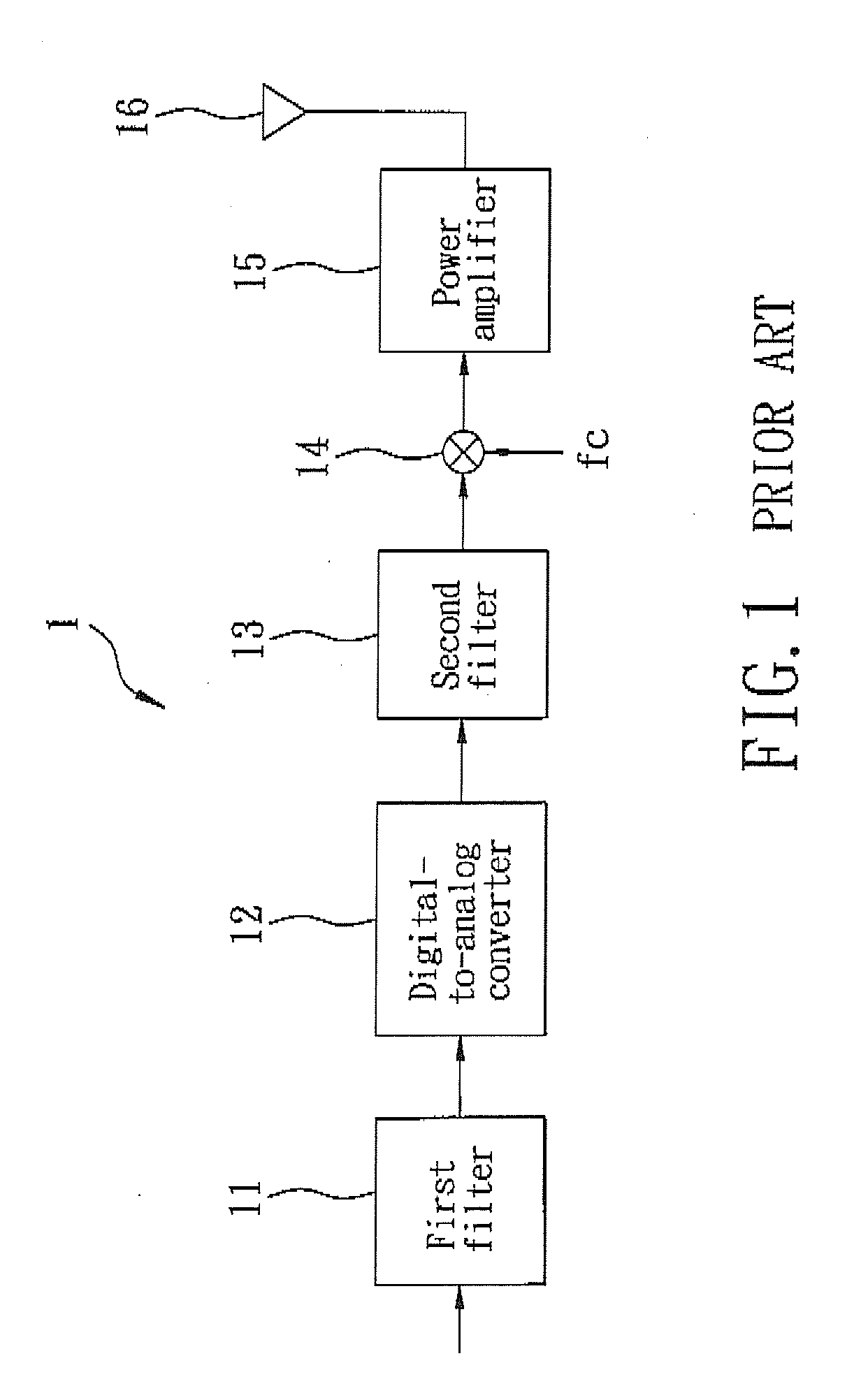
CROSS-REFERENCE TO RELATED APPLICATION[0001]This application claims priority of Taiwanese Application No. 096131086, filed on Aug. 22, 2007.BACKGROUND OF THE INVENTION[0002]1. Field of the Invention[0003]The present invention relates to a transmitter and a transmission method thereof, more particularly to a transmitter for wireless communication and a transmission method thereof.[0004]2. Description of the Related Art[0005]A wireless communication system transmits data through a channel with a predetermined frequency band. In order to reduce interference between wireless communication systems using different frequency bands, the energy outside of the frequency band used by each communication system is limited.[0006]Referring to FIG. 1, a conventional wireless communication system that operates in a predetermined frequency band includes a transmitter 1 and a receiver (not shown) The transmitter 1 converts an input signal into an output signal, and transmits the output signal to the r...

Claims


Application Information

Patent Timeline
Patent Type & Authority Applications(United States)
IPC IPC(8): H04B1/02
CPCH04B1/0483
Inventor LIN, YU-NANYEN, KUANG-YU
Owner REALTEK SEMICON CORP
Learn More