
Switching power supply circuit and household electrical appliance

A switching power supply circuit, switching tube technology, applied in the direction of instruments, electrical components, adjusting electrical variables, etc., can solve the problems of high voltage drift, device loss, multi-channel output voltage instability, etc., to improve stability, wide cross adjustment, etc. rate, the effect of reducing the output energy

Pending Publication Date: 2021-08-24
FOSHAN SHUNDE MIDEA ELECTRONICS TECH CO LTD +1
View PDF0 Cites 0 Cited by
  • Summary
  • Abstract
  • Description
  • Claims
  • Application Information

AI Technical Summary

Problems solved by technology

The non-feedback winding of the traditional flyback switching power supply scheme is prone to high voltage drift, resulting in device loss, so it is difficult to design multiple winding outputs, and the multi-channel output voltage is unstable

Method used


Image

  • Switching power supply circuit and household electrical appliance
  • Switching power supply circuit and household electrical appliance
  • Switching power supply circuit and household electrical appliance

Examples


Embodiment Construction

[0042] This part will describe the specific embodiment of the present invention in detail, and the preferred embodiment of the present invention is shown in the accompanying drawings. Each technical feature and overall technical solution of the invention, but it should not be understood as a limitation on the protection scope of the present invention.

[0043] In the description of the present invention, if the first and the second are described only for the purpose of distinguishing technical features, it cannot be understood as indicating or implying relative importance or implicitly indicating the number of indicated technical features or implicitly indicating The sequence of the indicated technical features.

[0044] In the description of the present invention, unless otherwise clearly defined, words such as setting, installation, and connection should be understood in a broad sense, and those skilled in the art can reasonably determine the specific meanings of the above w...


PUM


Abstract

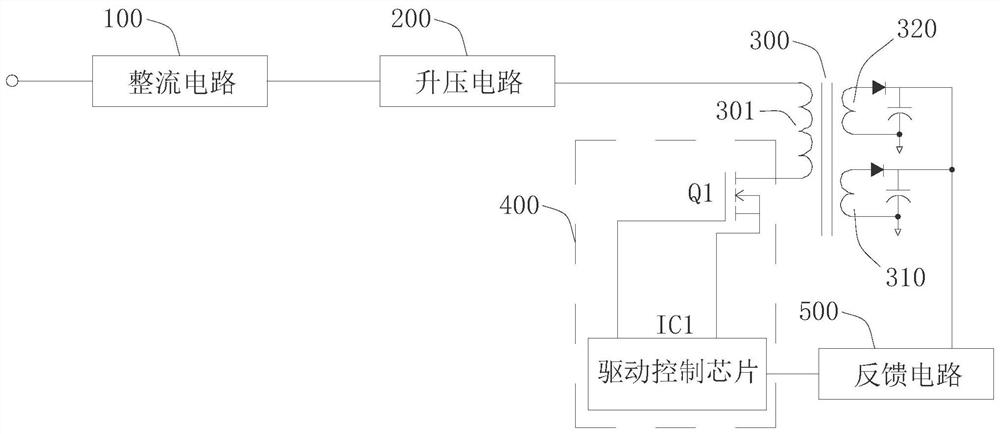
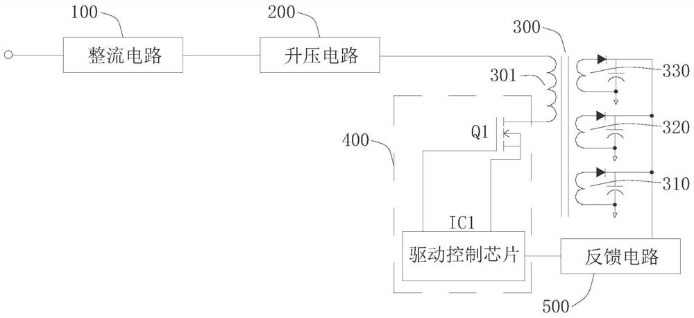
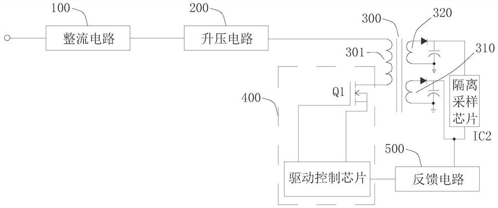
The invention discloses a switching power supply circuit and a household electrical appliance. The circuit comprises a rectification module, a boost circuit, a transformer, an input control circuit and a feedback circuit, wherein the boost circuit is connected with the output end of the rectification module; the transformer comprises a primary winding, a first secondary winding and a second secondary winding, and the primary winding is connected with the output end of the booster circuit; the input control circuit comprises a first switch tube connected with the primary winding and a driving control chip connected with the first switch tube; the input end of the feedback circuit is connected with the first secondary winding and the second secondary winding to detect the output voltage, and the output end of the feedback circuit is connected to the driving control chip. The output voltage of the first secondary winding and the output voltage of the second secondary winding are collected at the same time, that is, the feedback voltage is jointly acted by the output voltage of the multiple input windings, the wider cross adjustment rate is achieved, and the stability of the output voltage of the multiple windings can be improved.

Description

technical field [0001] The invention relates to the technical field of electronic circuits, in particular to a switching power supply circuit and household appliances. Background technique [0002] The flyback transformer switching power supply means that when the primary coil of the transformer is just excited by the DC pulse voltage, the secondary coil of the transformer does not provide power output to the load, but only after the excitation voltage of the primary coil of the transformer is turned off. To provide power output, this transformer switching power supply is called flyback switching power supply. [0003] The flyback switching power supply with multiple output windings has the problems of narrow cross regulation and unstable output voltage. Cross-regulation refers to the degree of influence on the adjacent winding when the load of the secondary output winding changes. The non-feedback winding of the traditional flyback switching power supply scheme is prone t...

Claims


Application Information

Patent Timeline
Patent Type & Authority Applications(China)
IPC IPC(8): H02M3/335H02M1/08H02M3/155
CPCH02M1/08H02M3/155H02M3/33507
Inventor 王慧锋
Owner FOSHAN SHUNDE MIDEA ELECTRONICS TECH CO LTD
Learn More