System and method for performing oilfield simulation operations

Active Publication Date: 2009-02-26
SCHLUMBERGER TECH CORP +2
View PDF19 Cites 49 Cited by
  • Summary
  • Abstract
  • Description
  • Claims
  • Application Information

AI Technical Summary

Benefits of technology

[0026]In general, in one aspect, the invention relates to a method of optimizing computer usage when performing simulations for a reservoir using a reservoir model wherein the reservoir model is gridded into cells. The method includes a. determining a preferred percentage of cells to be simulated using an Implicit Pressure, Explicit Saturations (IMPES) system for optimizing computer usage, b. determining a time-step for simulating the reservoir, c. calculating Courant-Friedrichs-Lewy (CFL) conditions according to the time-step for each cell of the reservoir model including calculating a temperature CFL condition, a composition CFL condition, and a saturation CFL condition, d. calculating a percentage of cells having no CFL condition with a value greater than one, e. determining whether the percentage calculated from step d is equal to or greater than the preferred percentage and if not, reducing the time-step and returning to step c, and f. simulating all cells having no CFL value greater than one using the IMPES system and simulating all other cells using a Fully Implicit Method (FIM) system.
[0027]In general, in one aspect, the invention relates to a computer system with optimized computer usag

Problems solved by technology

There are usually a large number of variables and large quantities of data to consider in analyzing oilfield operations.
The complexity of the physics that govern reservoir fluid flow leads to systems of coupled nonlinear partial differential equations

Method used


Image

  • System and method for performing oilfield simulation operations
  • System and method for performing oilfield simulation operations
  • System and method for performing oilfield simulation operations

Examples


Embodiment Construction

[0038]Presently preferred embodiments of the invention are shown in the above-identified Figs. and described in detail below. In describing the preferred embodiments, like or identical reference numerals are used to identify common or similar elements. The Figs. are not necessarily to scale and certain features and certain views of the Figs. may be shown exaggerated in scale or in schematic in the interest of clarity and conciseness.

[0039]In the following detailed description of embodiments of the invention, numerous specific details are set forth in order to provide a more thorough understanding of the invention. However, it will be apparent to one of ordinary skill in the art that the invention may be practiced without these specific details. In other instances, well-known features have not been described in detail to avoid unnecessarily complicating the description.

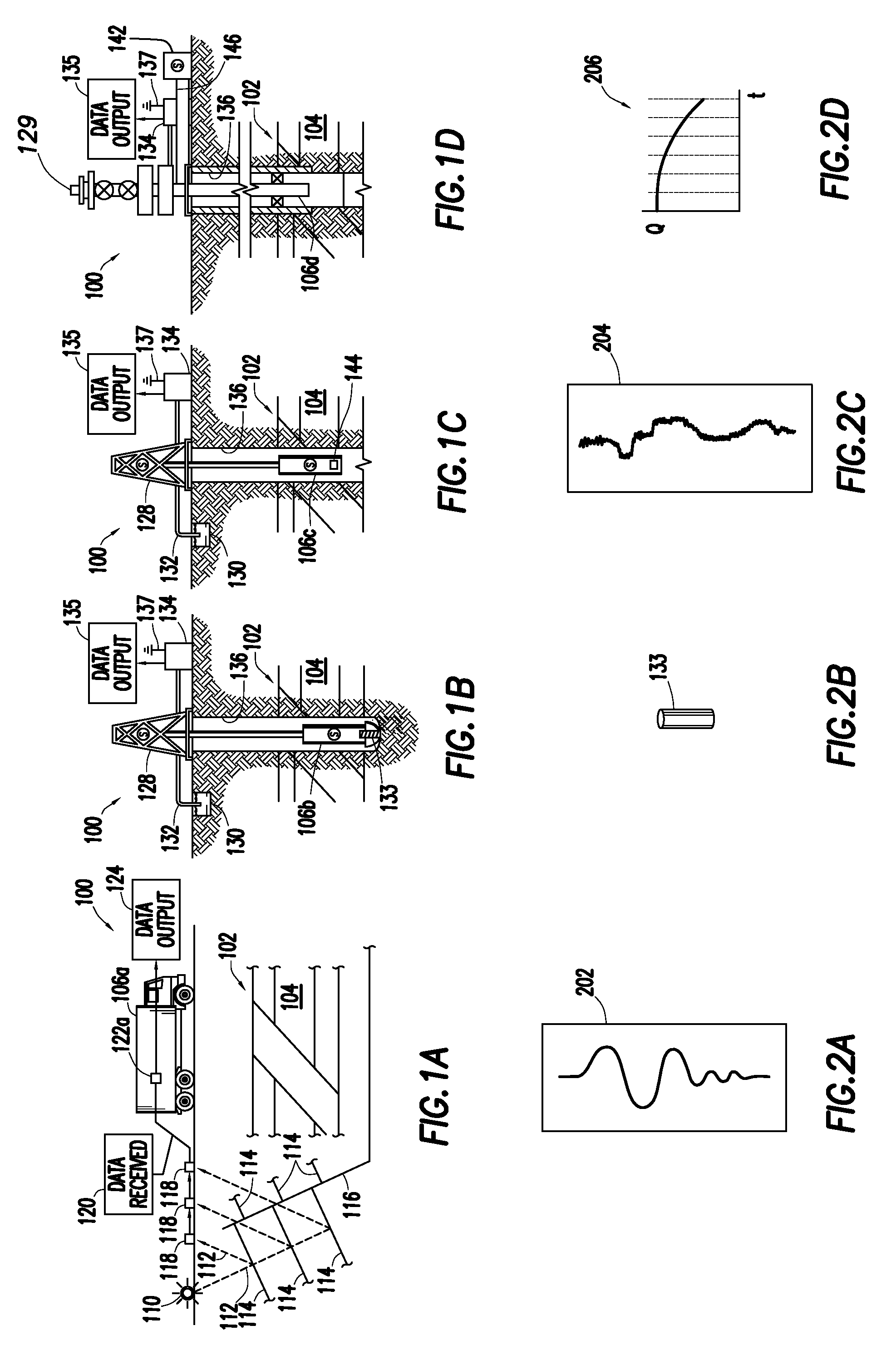
[0040]FIGS. 1A-D depict an oilfield (100) having geological structures and / or subterranean formations therein. As sh...


PUM


Abstract

The invention relates to a method of performing an oilfield operation of an oilfield having at least one wellsite, each wellsite having a wellbore penetrating a subterranean formation for extracting fluid from an underground reservoir therein. The method includes determining a time-step for simulating the reservoir using a reservoir model, the reservoir being represented as a plurality of gridded cells and being modeled as a multi-phase system using a plurality of partial differential equations, calculating a plurality of Courant-Friedrichs-Lewy (CFL) conditions of the reservoir model corresponding to the time-step, the plurality of CFL conditions being calculated for each of the plurality of gridded cells and comprising a temperature CFL condition, a composition CFL condition, and a saturation CFL condition calculated concurrently, simulating a first cell of the plurality of gridded cells using the reservoir model with an Implicit Pressure, Explicit Saturations (IMPES) system to obtain a first simulation result, the first cell having no CFL condition of the plurality of CFL conditions with a value greater than one, and simulating a second cell of the plurality of gridded cells using the reservoir model with a Fully Implicit Method (FIM) system to obtain a second simulation result, the second cell having at least one CFL condition of the plurality of CFL conditions with a value greater than one, and performing the oilfield operation based on the first and second simulation results.

Description

CROSS REFERENCE TO RELATED APPLICATIONS[0001]This application claims priority under 35 U.S.C. §119 to U.S. Provisional Patent Application No. 60 / 846,702, filed on Sep. 22, 2006.BACKGROUND[0002]1. Field of the Invention[0003]The present invention relates to techniques for performing oilfield operations relating to subterranean formations having reservoirs therein. More particularly, the invention relates to techniques for performing oilfield operations involving an analysis of reservoir operations, and the techniques impact on such oilfield operations.[0004]2. Background of the Related Art[0005]Oilfield operations, such as surveying, drilling, wireline testing, completions, simulation, planning, and oilfield analysis, are typically performed to locate and gather valuable downhole fluids. Various aspects of the oilfield and its related operations are shown in FIGS. 1A-1D. As shown in FIG. 1A, surveys are often performed using acquisition methodologies, such as seismic scanners to gene...

Claims


Application Information

Patent Timeline
IPC IPC(8): G06F7/60G06F17/10
CPCE21B49/00E21B43/00
Inventor MONCORGE, ARTHURTCHELEPI, HAMDI A.
Owner SCHLUMBERGER TECH CORP
Why Eureka
Try Eureka