
Monitoring distributed applications

a technology of distributed applications and monitoring, applied in the field of monitoring distributed applications, can solve the problems of inefficient operation of hardware systems, the need for seemingly more complex software continues to grow, and the complexity of software and hardware employed in such systems

Active Publication Date: 2009-02-26
MICROSOFT TECH LICENSING LLC
View PDF65 Cites 54 Cited by
  • Summary
  • Abstract
  • Description
  • Claims
  • Application Information

AI Technical Summary

Benefits of technology

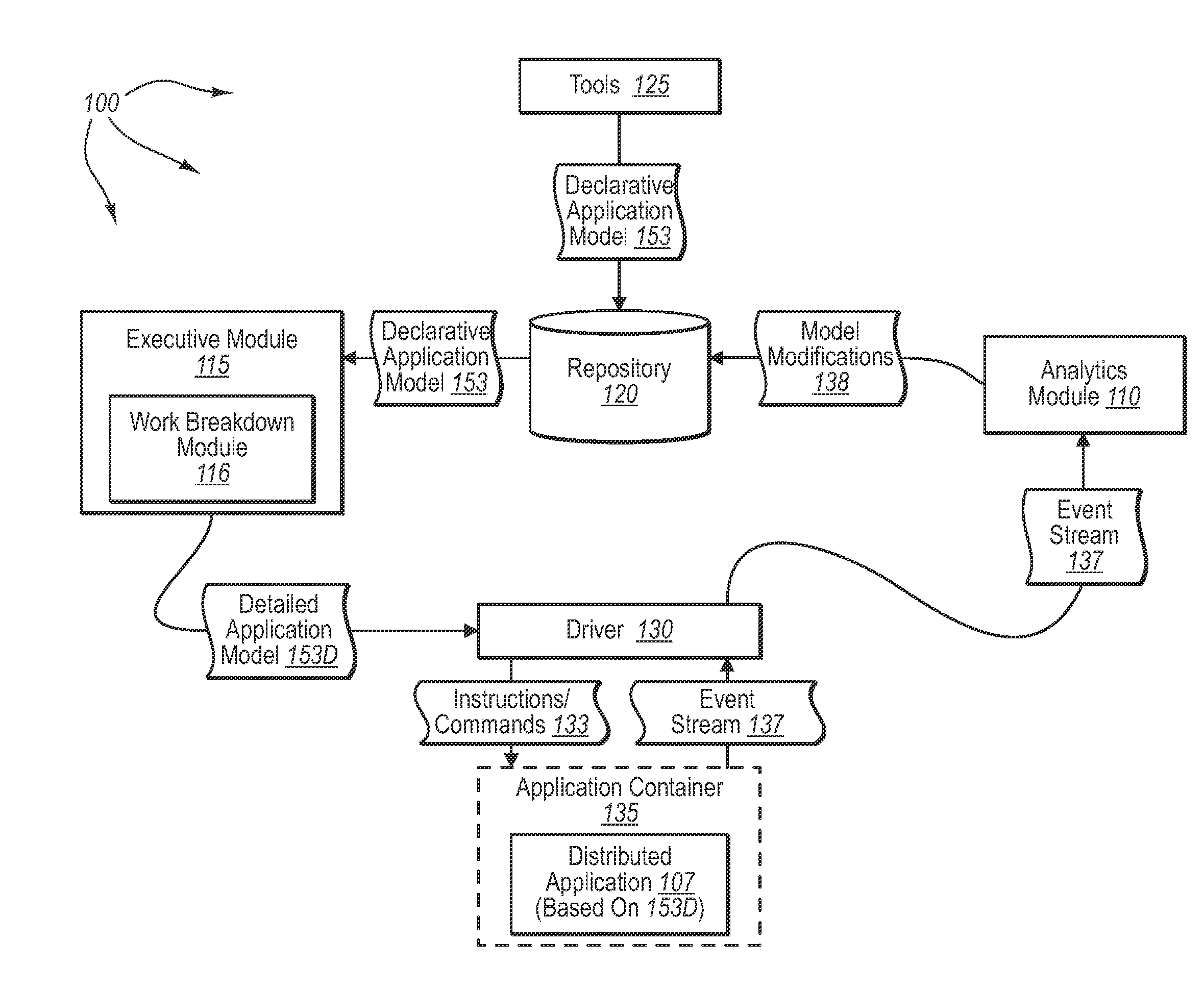
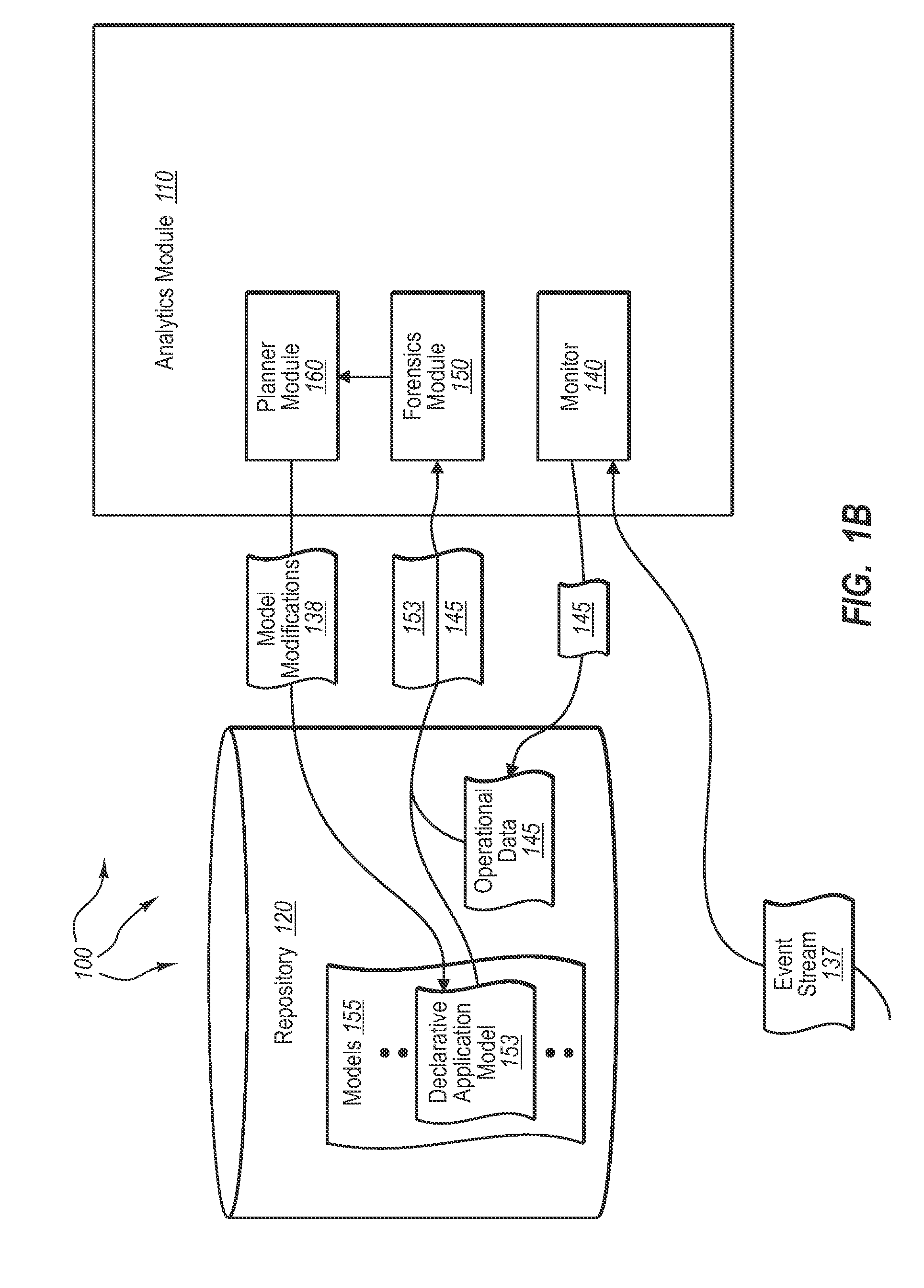
[0024]An application monitoring event flow is activated based on the application monitoring event flow graph. A monitor monitoring event flow is subsequently activated based on the activated application monitoring event flow. The monitor monitoring event flow is for receiving and processing emitted events associated with monitoring the application in order to create monitor operational data. An event associated with the deployed application is received. The received event is processed in accordance with the application monitoring event flow. Processing triggers events regarding the monitoring itself (such as when events are processed by event operators). The triggered event is processed in accordance with

Problems solved by technology

As computerized systems have increased in popularity, so have the complexity of the software and hardware employed within such systems.
In general, the need for seemingly more complex software continues to grow, which further tends to be one of the forces that push greater development of hardware.
For example, if application programs require too much of a given hardware system, the hardware system can operate inefficiently, or otherwise be unable to process the application program at all.
Unfortunately, conventional distributed application servers are typically ill-equipped (or not equipped at all) to automatically handle and manage all of the different complexities associated with distributed application.
Such accommodations, however, can be difficult if not impossible to do with conventional distributed application server platforms.
Specifically, most conventional distributed application server platforms are ill-equipped or otherwise unable to identify and properly manage different demand patterns between components of a distributed application program.
This is due at least partly to the complexity in managing application programs that can have many distributed components and subsystems, many of which are long-running workflows, and / or otherwise legacy or external systems.
In addition, conventional distributed application program servers are generally not configured for efficient scalability.
As such, when an administrator desires to redeploy certain modules or components onto another server or set of computer systems, there is always some (and potentially a significant) possibility of redeployment causing errors to occur (e.g., due to differences in network protocols, system configurations, etc.) These errors can result when messages are not passed onward everywhere they are needed, or if they are passed onward incorrectly.
Due to these and other complexities, distributed application programs tend to be fairly sensitive to sharply increasing demands (i.e., demand spikes).
For example, sharply increasing demands can cause various distributed application modules to operate at a sub-optimum level for significant periods of time before the sub-optimum performance is detected.
In some cases, an administrator (depending on skill and experience) may not even attempt corrective action, since improperly implemented corrective action can cause further operational problems.
Thus, a distributed application module could potentially become stuck in a pattern of inefficient operation, such as continually rebooting itself, without ever getting corrected during the lifetime of the distributed application program.
However, these monitoring techniques suffer from a variety of inefficiencies.
Unfortunately, since the instrumentation code is essentially built into the distributed application there is little, if any, mechanism that can be used to regulate the type, frequency, and contents of produced events.
As a result of the inability to regulate produced monitoring events, there is typically no way during execution of distributed application to adjust produced monitoring events (e.g., event types, frequencies, and content) for a particular purpose.
Thus, it can be difficult to dynamically configure a distributed application to produce monitoring events in a manner that assists in monitoring and correcting a specific undesirable application behavior.
Further, the monitoring system itself, through the unregulated production of monitoring events, can aggravate or compound existing distributed application problems.
For example, the production of monitoring events can consume significant resources at worker machines and can place more messages on connections that are already operating near capacity.
However, monitoring modules typically lack any ability to alter distributed application configuration, at least due to the instrumentation code being built into the distributed application.
Thus, filtering typically occurs near the end of the monitoring process and can not be used to reduce the consumption of worker machine resources and / or network capacity associated with the production of monitoring events.
Additionally, when source code for a distributed application is compiled (or otherwise converted to machine-readable code), a majority of the operating intent of the distributed application is lost.
Thus, a monitoring module has limited, if any, knowledge, of the intended operating behavior of a distributed application when it monitors the distributed application.
Accordingly, during distributed application execution, it is often difficult for a monitoring module to determine if undesirable behavior is in fact occurring.
However, this provides the monitoring module with limited and often incomplete knowledge of the intended application behavior.
However, based on information from received monitoring events, it can be difficult, if not impossible, for a monitor module to determine that the production of seven messages a second is not intended.

Method used


Image

  • Monitoring distributed applications
  • Monitoring distributed applications
  • Monitoring distributed applications

Examples


Embodiment Construction

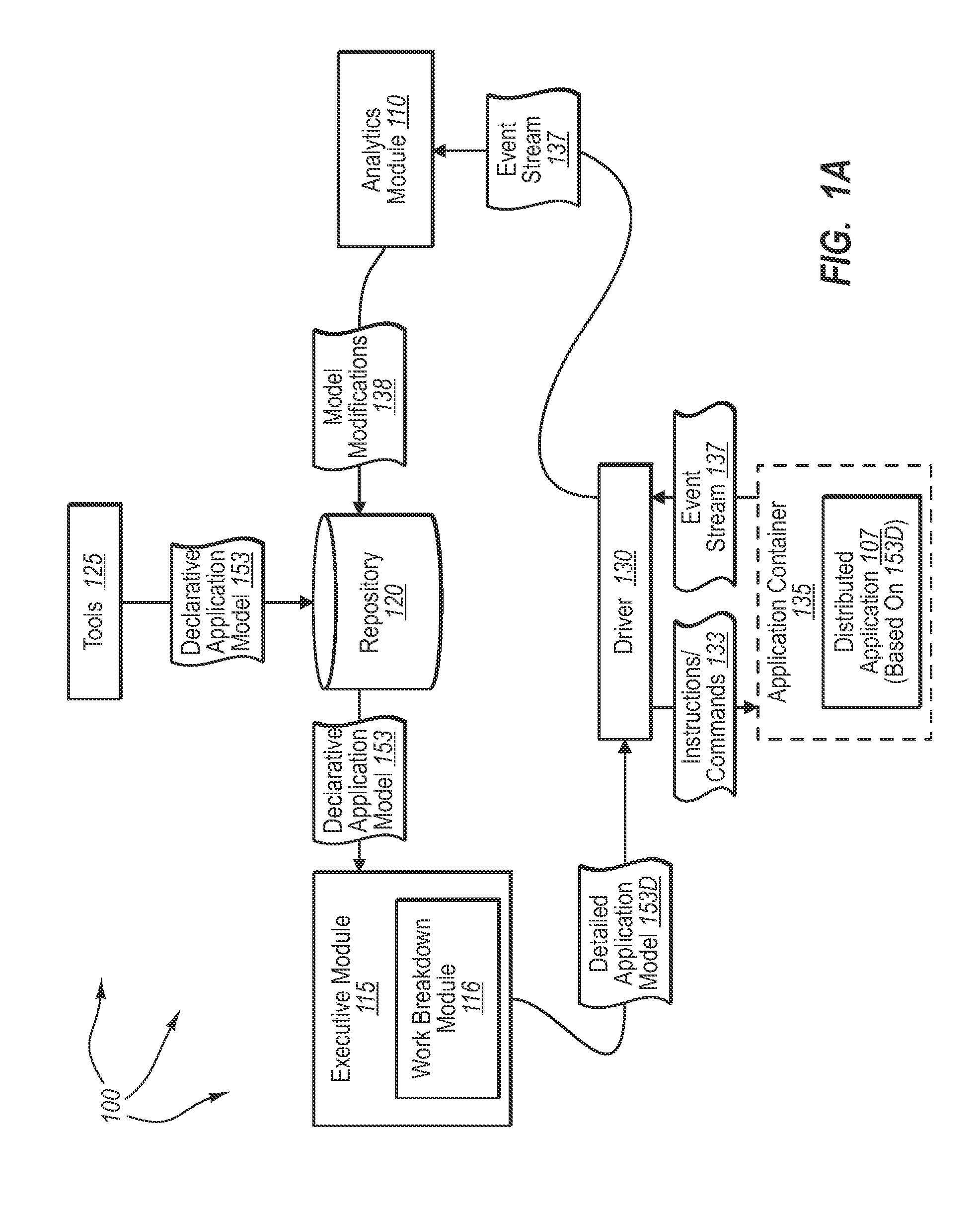
[0032]The present invention extends to methods, systems, and computer program products for monitoring distributed applications. In some monitoring embodiments, a computer system accesses a declarative application model describing application intent. The declarative application model indicates events that are to be emitted from applications deployed in accordance with the application intent. An application is deployed in accordance with the declarative application model. The computer system accesses a declarative observation model. The declarative observation model describes how emitted events, received from an application deployed in accordance with the application intent, are to be aggregated and processed to produce relevant operational data for the application

[0033]The declarative application model and the declarative observation model are compiled into an event flow graph for monitoring the behavior of the application. The event flow graph includes connected event streams and ev...


PUM


Abstract

The present invention extends to methods, systems, and computer program products for monitoring distributed applications. Declarative application models are used. Operational data for a deployed application can be compared to an application intent expressed in a corresponding declarative application to provide more effective monitoring of application behavior. Application components can subscribe to an event fabric to receive configurations that indicate what events the application is to emit (i.e., publish into the event fabric) for monitoring. Thus, applications essentially subscribe to produce information (as opposed to subscribing to receive information). Monitoring can be dynamically adjusted in response to environment changes.

Description

CROSS-REFERENCE TO RELATED APPLICATIONS[0001]N / A.BACKGROUNDBackground and Relevant Art[0002]Computer systems and related technology affect many aspects of society. Indeed, the computer system's ability to process information has transformed the way we live and work. Computer systems now commonly perform a host of tasks (e.g., word processing, scheduling, accounting, etc.) that prior to the advent of the computer system were performed manually. More recently, computer systems have been coupled to one another and to other electronic devices to form both wired and wireless computer networks over which the computer systems and other electronic devices can transfer electronic data. Accordingly, the performance of many computing tasks are distributed across a number of different computer systems and / or a number of different computing components.[0003]As computerized systems have increased in popularity, so have the complexity of the software and hardware employed within such systems. In g...

Claims


Application Information

Patent Timeline
IPC IPC(8): G06F9/45G06F9/44
CPCG06F11/3612
Inventor SEDUKHIN, IGORCHKODROV, GUEORGUI BONOVKULKARNI, AMOL SUDHAKARBORSA, MARIUSZ GERARDWU, HAORAN ANDYESHNER, DANIELZUNINO, GILLES C.J.A.
Owner MICROSOFT TECH LICENSING LLC
Learn More