Engine with cylinder disabling mechanism

a technology of disabling mechanism and cylinder, which is applied in the direction of combustion engines, valve arrangements, machines/engines, etc., can solve the problems of difficult to define the oil passages in the crankcase and the cylinder block, and achieve the effect of easy installation and convenient installation

Inactive Publication Date: 2009-03-05
HONDA MOTOR CO LTD
View PDF1 Cites 3 Cited by
  • Summary
  • Abstract
  • Description
  • Claims
  • Application Information

AI Technical Summary

Benefits of technology

[0010]According to an embodiment of the present invention, since the oil passage to the hydraulic pressure control valve includes an externally mounted pipe, the oil passage can be installed more easily than if it is defined in the crankcase and the cylinder block as is the case with the background art.
[0011]If the oil passage is disposed on a rear surface of the engine, the pipe is complex and long because of functional components including an intake system, a starter motor, a knock sensor, a coolant hose, etc. The oil passage disposed on the front surface of the engine allows the pipe to be short and easily installed.

Problems solved by technology

Heretofore, it has been difficult to define the oil passages in the crankcase and the cylinder block.

Method used


Image

  • Engine with cylinder disabling mechanism
  • Engine with cylinder disabling mechanism
  • Engine with cylinder disabling mechanism

Examples


Embodiment Construction

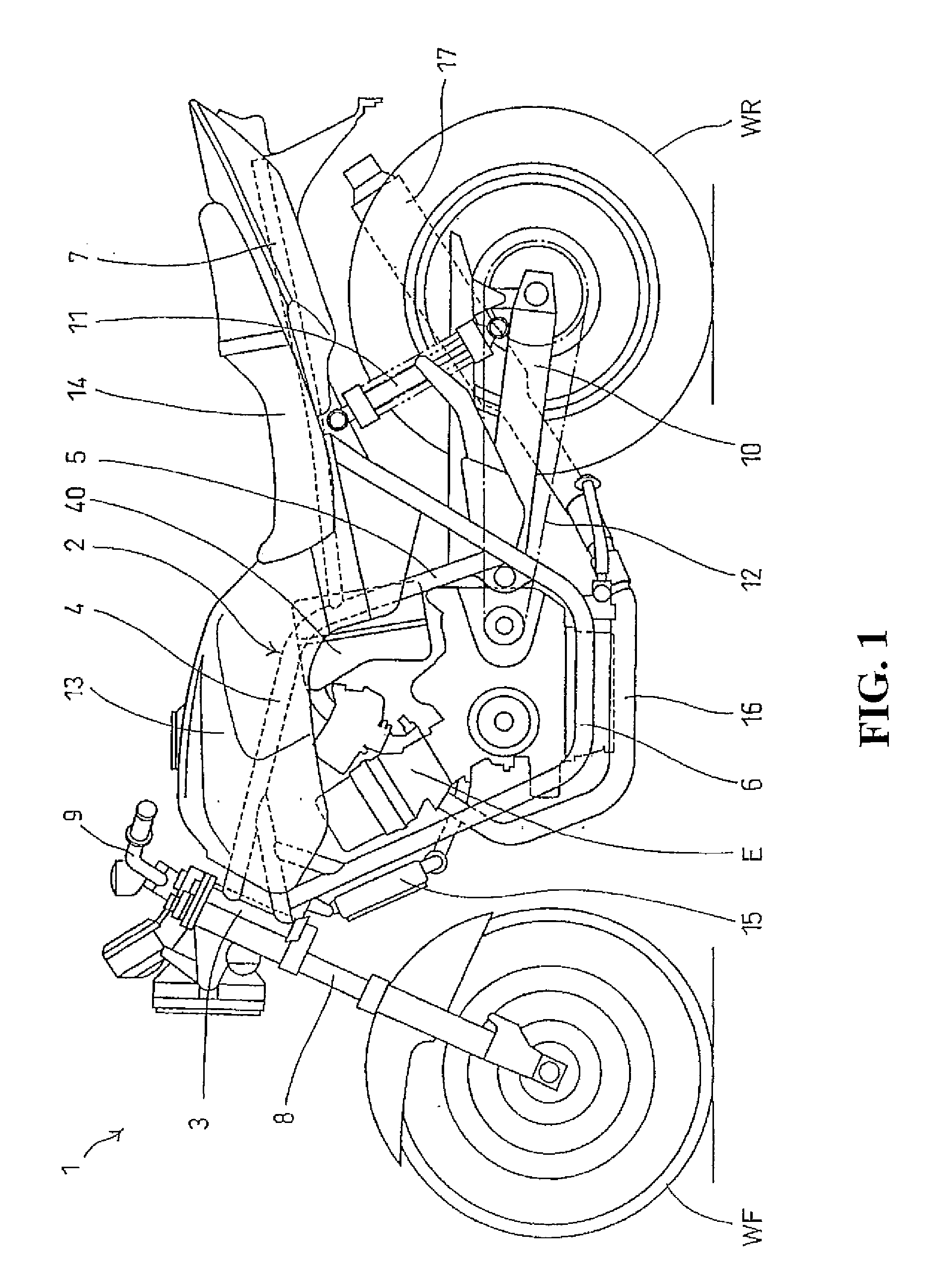
[0025]FIG. 1 is a side elevational view of a motorcycle 1 according to an embodiment of the present invention. In FIG. 1, the motorcycle 1 includes a body frame 2 including a head pipe 3, main frames 4, 4 extending obliquely rearwardly from the head pipe 3, central frames 5, 5 extending downwardly from the rear ends of the main frames 4, 4, down pipes 6, 6, and a seat stay 7 extending rearwardly from the main frames 4, 4 and the down pipes 6, 6. A front wheel WF is supported by a front fork 8 which is steerably supported by the head pipe 3. A steering handle 9 is mounted to an upper portion of the front fork 8. A rear wheel WR is supported by a rear fork 10 that is vertically swingably supported by a rear portion of one of the central frames 5. A shock absorber 11 is disposed between the seat stay 7 and the rear fork 10. An engine E is supported by the main frames 4, 4 and the central frames 5, 5. Power from the engine E is transmitted to the rear wheel WR through a transmission com...


PUM


Abstract

An engine includes engine valves disposed on intake and exhaust sides of a combustion chambers with a valve operating device for opening and closing the engine valves and an engine valve disabling mechanism for disabling opening and closing movement of the engine valves in response to hydraulic pressure. An oil pump is disposed in a lower portion of the crankcase, for supplying hydraulic pressure to the engine valve disabling mechanism. A hydraulic pressure control valve controls the supply of hydraulic pressure to the engine valve disabling mechanism depending on a vehicle operating state. An oil passage extends to the hydraulic pressure control valve and can easily be formed without affecting mounts for functional components. A pipe for delivering working oil from the lower portion of the crankcase to the hydraulic pressure control valve is disposed on a front surface of the engine.

Description

CROSS-REFERENCE TO RELATED APPLICATIONS[0001]The present application claims priority under 35 USC 119 to Japanese Patent Application No. 2007-224989 filed on Aug. 31, 2007 the entire contents of which are hereby incorporated by reference.BACKGROUND OF THE INVENTION[0002]1. Field of the Invention[0003]The present invention relates to an engine with a cylinder disabling mechanism, and more particularly to a hydraulic pressure supply oil passage for supplying hydraulic pressure to hydraulic pressure control valves for controlling the supply of the hydraulic pressure to the cylinder disabling mechanism.[0004]2. Description of Background Art[0005]Engines are known wherein the engines have a valve disabling mechanism associated with engine valves. According to the valve disabling mechanism, oil is delivered from an oil pump disposed in a lower portion of the engine to hydraulic pressure control valves, which controls hydraulic pressure delivered to the valve disabling mechanism to disable...

Claims


Application Information

Patent Timeline
Patent Type & Authority Applications(United States)
IPC IPC(8): F02D17/02
CPCF01L1/143F01L13/0005Y02T10/18F02B61/02F02D13/06F01L2001/0537Y02T10/12
Inventor MAEHARA, HAYATOSATO, TOSHIYUKITSUKUI, TAKAAKI
Owner HONDA MOTOR CO LTD
Why Eureka
Try Eureka