Vertical Continuous Vacuum Pan

Inactive Publication Date: 2009-03-05
SPRAY ENG DEVICES
View PDF2 Cites 4 Cited by
  • Summary
  • Abstract
  • Description
  • Claims
  • Application Information

AI Technical Summary

Benefits of technology

[0053]A search of the prior art reveals that though it is highly desirable to have a single vertical continuous vacuum pan of eight chambers for optimum product quality, yet the same has not been implemented at commercial level, due to technical difficulties and economy. The existing apparatus in the state of the art consists of four or five stirrer equipped chambers arranged one on top of the other, occupying a total height of around 31 meters. In the present invention, within the approximately same height, instead of four or five chambers, eight chambers alongwith an additional storage / buffer tank, have been incorporated by using a novel approach. According to this approach, the intermediate space between the chambers which was housing the mechanical circulator drives and gearboxes, has been altogether eliminated without using common shafts for mechanical circulators (stirrers), by housing the drives in specially insulated pockets in the vapor space in each chamber. In addition, another novel approach has been adopted in making the drives bottom mounted, resulting in considerable reduction in shaft length, from 5.0-6.0 meters in existing apparatus to just 0.5-0.56 meters in the present invention, enabling easy installation and maintenance and resulting in power economy.STATEMENT OF INVENTION
[0054]Accordingly, the present invention provides an improved vertical continuous vacuum pan comprising a cylindrical housing having a vertical axis in which plurality of vacuum chambers are stacked one above the other on a common axis characterized in that each chamber has a bottom mounted mechanical circulator housed in an insulated pocket in the vapour space segment of each chamber and not in additional space above the chamber enabling erection of at least eight operation vacuum chambers and a storage or buffer tank at top of the cylindrical housing, in the same height in which previously only 4 or 5 operation chambers were erected, thus eliminating the need for erecting two upright standing towers.

Problems solved by technology

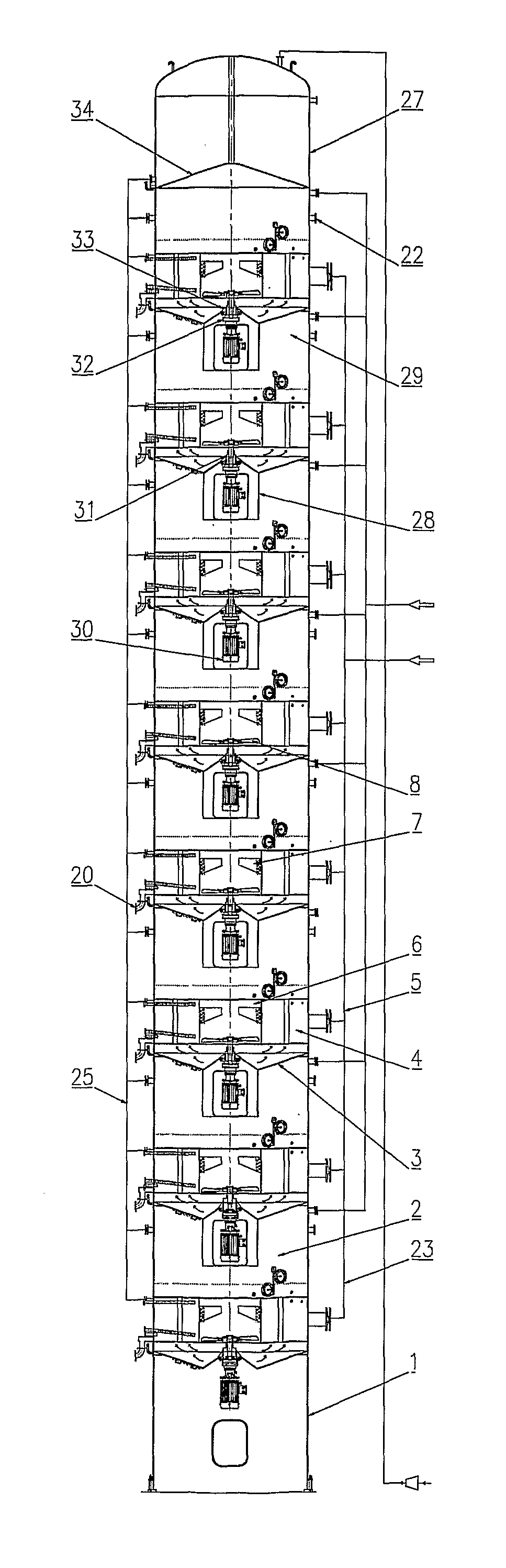
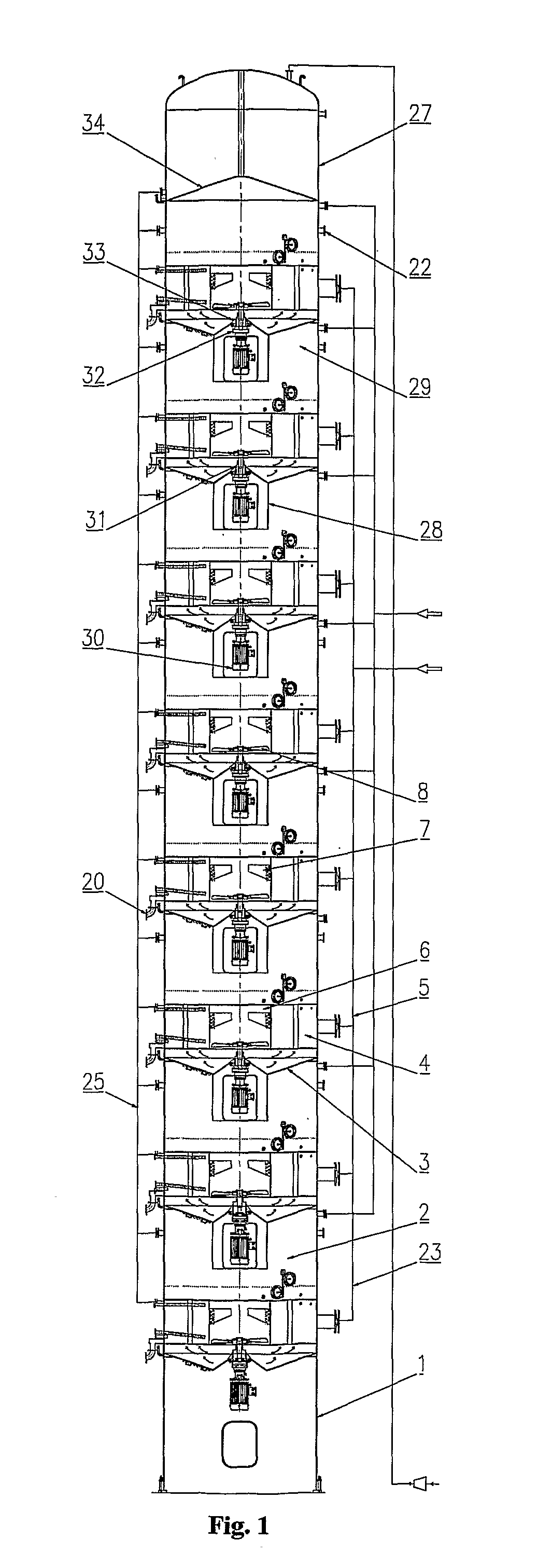
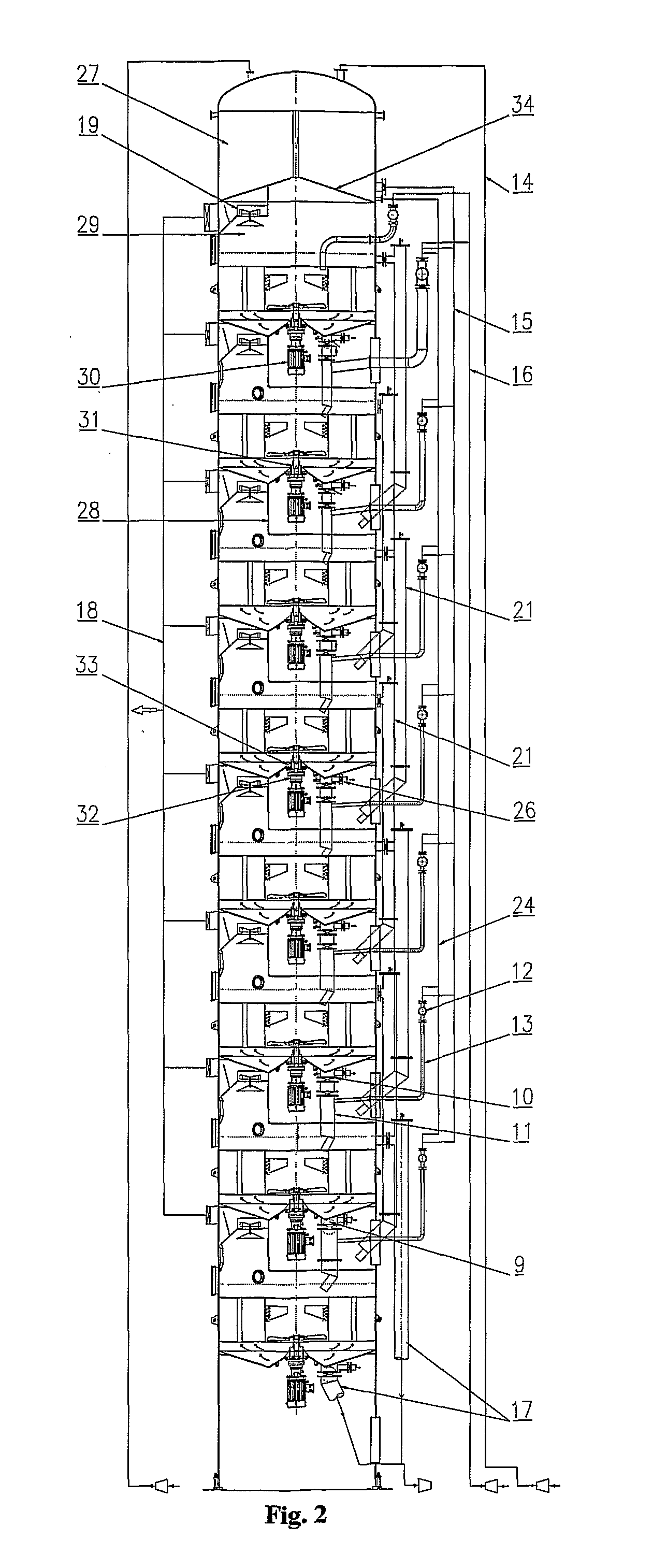
However, it had the following disadvantages:1. Efficiency: Low efficiency of the crystallizer-evaporator due to all stages being performed in one vessel only;2. Steam consumption: higher both quantitatively and qualitatively;3. Product quality: Slow and uneven growth rates.4. Dead Time: It is the time during which one process is completed and the next has to be started.
Since, the process was discontinous, time gap had to be given to clean the vessel and make it operational for a fresh batch, resulting in ‘dead time.’5. Variable load: Fluctuating heating steam demand and variable vapour pressure requirements resulting in higher energy consumption, uneven load on boiler and condenser respectively, resulting in increased cost of production and lowered efficiency of operations.
These disadvantages led to the development of continuous vacuum pans wherein process is carried out by continuously feeding the seed crystals and the sugar solution to an evaporator-crystallizer, while withdrawing the massecuite (highly concentrated suspension) from the evaporator-crystallizer.
However, the horizontal type continuous vacuum pan had several disadvantages viz.a) Product quality variable: large variation in size of final crystals due to short-circuiting of the massecuite flow-path;b) Processing difficulties: high-purity syrups were difficult to process;c) Incrustation problem: prone to incrustations, especially in the openings between the compartments.
Incrustations are not a desirable feature as they lower heat transfer efficiency and hinder circulation / movement of syrup, reducing yield;d) Lack of By-passing provision: In horizontal type, all compartments are interconnected and placed in the same vessel.
Hence, in event of maintenance of any one compartment, entire unit has to be halted.e) Quality reduction in final product: conglomeration & false grain formation is more leading to reduction in quality of final product.e) Yield reduction: short-circuiting and splashing of massecuite from one compartment to other led to poor or reduced yield.f) Higher space requirement: requires considerably higher floor space.
It may not be possible for a factory using an older type batch pan with mechanical agitator which utilizes much lesser space, to replace it with a continuous horizontal pan.g) Complex and Costly Design: Continuous vacuum pans have complex and costly design with non-identical compartments.
Various attempts, in horizontal continuous vacuum pans, to remedy the above disadvantages resulted in undesirable complications in apparatus and control systems making the structural and process engineering factors unfavourable.
It was realized that disadvantages of the horizontal system, especially those connected with the quality of the product crystals viz. large crystal size variation, conglomeration, false grain formation, etc. also arise due to different conditions at separate stages in a pan.
A reliable operation without stirrers (mechanical circulation) is not possible and may lead to sedimentation of the crystals (Austmeyer, K. E.; Schliephake, D.; Ekelhof, B.; Sittel, G.
However, such an arrangement violates a fundamental feature of vertical continuous vacuum pans viz. stirrers mounted on a common shaft present a disadvantage when one of the chambers is taken out of operation for cleaning or other reasons.
The underlying cause for it was the limited number of stirrer-equipped evaporating-crystallization chambers.
However, for economic reasons, this concept could not be implemented till date.
Major problems associated with an increase in number of treatment chambers are as follows:1. Increased height of the apparatus;2. Stirrer shaft becomes very long, both in case of top mounted motor of the mechanical stirrer and in case of stirrers mounted on a common shaft.3. Associated technical problems: e.g. installation complexities, maintenance problems, increased noise levels, alignment / guidance requirements, etc.
From the above, it is clear that though vertical type continuous apparatus offered distinct advantages over the horizontal system, it also had technical limitations regarding the number of stages which could be incorporated in a single apparatus.
However, such a ‘twin-tower’ arrangement also has disadvantages.i) It adds to energy requirements e.g. pumping andii) leads to decrease in overall performance and efficiency of the system besides the disadvantages mentioned above.iii) Also there are problems associated with the bypassing of chambers in such an arrangement.

Method used


Image

  • Vertical Continuous Vacuum Pan
  • Vertical Continuous Vacuum Pan
  • Vertical Continuous Vacuum Pan

Examples


Embodiment Construction

[0058]The present invention consists of an improved vertical continuous vacuum pan apparatus consisting of eight chambers and a storage tank at the top, within the existing conventional height (FIGS. 1 & 2), characterized in that each chamber has a bottom mounted drive housed in an insulated pocket in the vapour space segment of each chamber and not in additional space above the chamber. As a result, the technical problems associated with multiplicity of chambers have been solved in the present invention. Increasing the number of compartments in a vertical apparatus has distinct advantages of increasing product quality, besides economy of operation. However economic limitations prevented the increase in height of the apparatus which could result in number of chambers being increased. Also, technical problems associated with the positioning, installation and maintenance of the stirrer (circulator) drives prevented an increase in the number of chambers within the same apparatus height...


PUM


Abstract

The present invention consists of an improved vertical continuous vacuum pan apparatus consisting of eight chambers (2) (instead of four or five) and a storage or buffer tank (27) at the top, within the existing conventional height, characterized in that each chamber has a bottom mounted mechanical circulator housed in an insulated pocket (28) in the vapour space segment (29) of each chamber and not in additional space above the chamber.

Description

FIELD OF INVENTION[0001]This invention relates to an improved apparatus for the continuous crystallization of a substance from a solution, using vacuum pan and more particularly, but not exclusively, to continuous crystallization of sugar from a solution in a vertical continuous vacuum pan.BACKGROUND TO THE INVENTION (PRIOR ART)[0002]Definition of Important Terms:[0003]1. Massecuite: (Pronounced=Mess-kit)[0004]It is a mixture of crystals and mother liquor discharged from a vacuum pan.[0005]2. Calandria: Equipment consisting of closely spaced metal tubes for heat exchange.[0006]The present invention describes an improved apparatus for the continuous production of sugar. The apparatus consists of multiple vacuum chambers or operation chambers arranged vertically, one top of the other. The chambers perform the function of crystallization and evaporation. Each chamber is vertically connected to the next, so that sugar syrup after reaching a particular consistency on undergoing evaporati...

Claims


Application Information

Patent Timeline
IPC IPC(8): C13F1/02C13B30/02C13B25/00C13B25/02C13B25/06
CPCC13B25/02C13B30/025C13B30/007C13B25/06
Inventor SINGH, JAI PARKASHGUPTA, VIPIN KUMARSINGH, SAROJ KUMAR
Owner SPRAY ENG DEVICES
Why Eureka
Try Eureka