Protector and fluid filter using same

a technology of fluid filter and protector, which is applied in the direction of filtration separation, membrane technology, separation processes, etc., can solve the problems of difficult assembly, decreased operational precision, and inability to assemble protectors, etc., and achieves the effect of easy assembly, simple assembly, and easy assembly

Inactive Publication Date: 2009-03-05
TOYOTA BOSHOKU KK
View PDF13 Cites 13 Cited by
  • Summary
  • Abstract
  • Description
  • Claims
  • Application Information

AI Technical Summary

Benefits of technology

[0059]According to the protector and the fluid filter using the protector of the present invention, the support and the pedestal are made of resin, and the snap fit structure constituted by the first joint portion and the second joint portion is provided. Therefore, the protector can be assembled easily simply by fitting together the support and the pedestal by a manual operation.
[0060]Hence, in contrast to a conventional case in which caulking retention and rivet retention using specialized tools is required, the protector can be assembled easily by a manual operation even in a factory where sufficient tools are not available. Furthermore, the snap fit structure constituted by the joint portions is provided, and therefore the protector can be assembled correctly without the need for strict positioning of the support and the pedestal. Hence, the protector can be assembled easily and accurately by a manual operation.
[0061]Moreover, in comparison with a conventional protector that requires rivet retention, the number of components of the protector can be reduced since rivets are not required. Furthermore, protectors having different lengths can be assembled easily simply by attaching supports of differing lengths, and therefore protectors of various lengths can be assembled with a small number of types of components.
[0062]Further, when the transverse rib is provided in the interior of the cylindrical portion of the support, the strength of the support can be increased, and the protector and filter element can be prevented from being crushed even when high-pressure fluid flows through the fluid filter.
[0063]Further, when the first joint portion includes the pawl portion and the second joint portion includes the engaging portion that engages with the pawl portion, the support and the pedestal can be connected easily and reliably by the engagement between the pawl portion and the engaging portion.
[0064]Further, even when an attempt is made to fit together the support and the pedestal by applying excessive force while the pawl portion and the engaging rib are in contact with each other, the support and the pedestal are rotated in the axial direction of the cylindrical portion by the inclined surfaces on the tip end surface of the pawl portion and the end surface of the engaging rib so as to be guided to their correct positions, and therefore damage to the support and the pedestal and so on can be prevented.

Problems solved by technology

Moreover, specialized tools are required to retain the caulking and the rivet, and therefore assembly becomes difficult in locations where sufficient tools are not available or the operational precision decreases, for example overseas.
In this case, however, a specialized rivet retention tool that is appropriate for the length must be used, and therefore it is not easy to assemble protectors 100 having different lengths.

Method used


Image

  • Protector and fluid filter using same
  • Protector and fluid filter using same
  • Protector and fluid filter using same

Examples


embodiments

[0104]Specific embodiments of the present invention will be described below using the drawings. Note that in each embodiment, an oil filter that is attached to a cylinder block (not shown) of an internal combustion engine so as to filter oil for lubricating the interior of the cylinder block is employed as an example of the “fluid filter” according to the present invention.

first embodiment

1. First Embodiment

(1) Constitution of Oil Filter

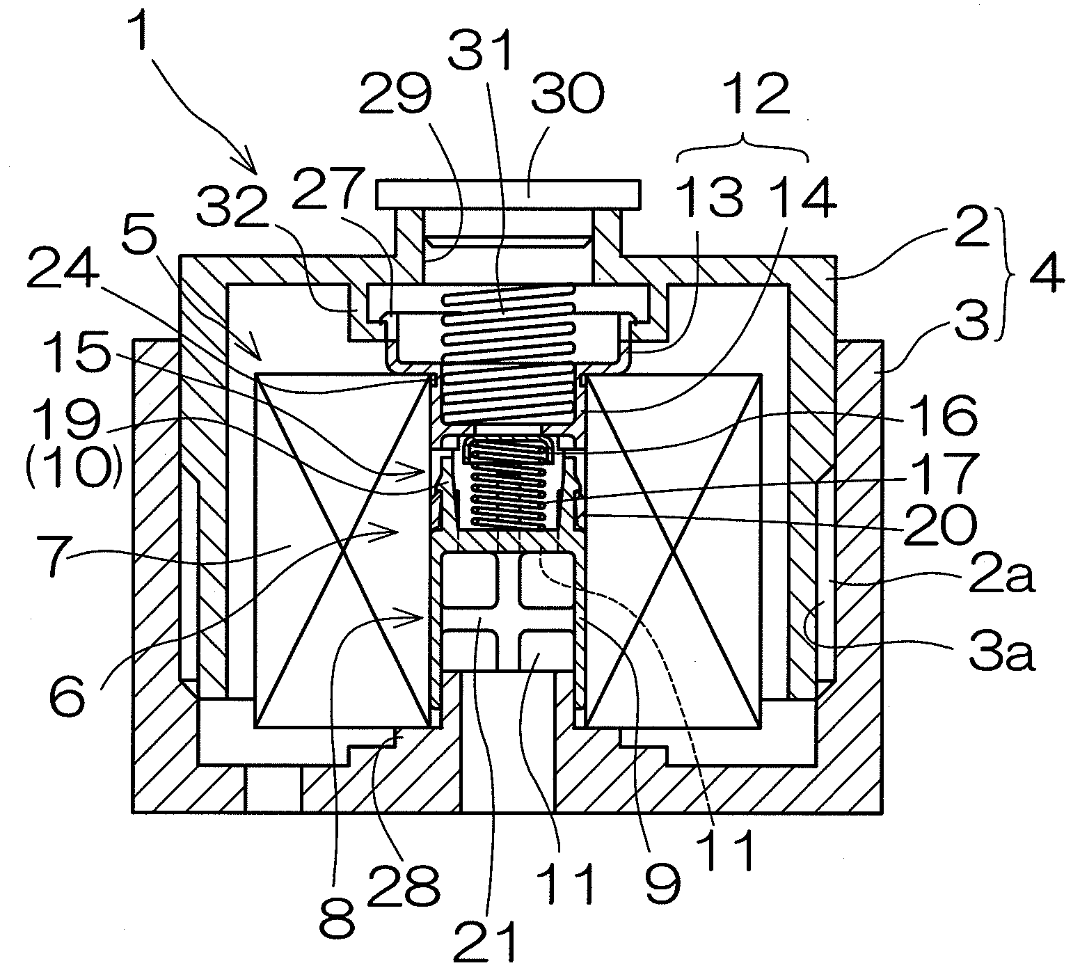
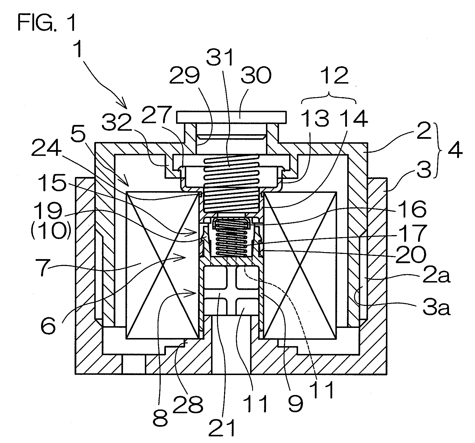
[0105]As shown in FIG. 1, an oil filter 1 according to a first embodiment includes a casing 4 constituted by a closed-end cylindrical cap 2 and a base 3 that are made of metal and can be screwed together through relative rotation.

[0106]A male screw portion 2a is formed on an outer peripheral surface of the cap 2, and an O-ring (not shown) is attached thereto. Further, a female screw portion 3a is formed on an inner peripheral surface of the base 3. When the male screw portion 2a and the female screw portion 3a are screwed together, the interior of the casing 4 is sealed by the O-ring and thereby maintained in a liquid-tight condition.

[0107]An element assembly 5 is housed in the interior of the casing 4. The element assembly 5 is formed by attaching a cylindrical filter element 7 to an outer periphery of a substantially cylindrical protector 6, and is sandwiched between the cap 2 and the base 3.

[0108]The filter element 7 is formed by f...

second embodiment

2. Second Embodiment

(1) Constitution of Oil Filter

[0126]As shown in FIG. 1, an oil filter 1 according to a first embodiment includes a casing 4 constituted by a closed-end cylindrical cap 2 and a base 3 that are made of metal and can be screwed together through relative rotation.

[0127]A male screw portion 2a is formed on an outer peripheral surface of the cap 2, and an O-ring (not shown) is attached thereto. Further, a female screw portion 3a is formed on an inner peripheral surface of the base 3. When the male screw portion 2a and the female screw portion 3a are screwed together, the interior of the casing 4 is sealed by the O-ring and thereby maintained in a liquid-tight condition.

[0128]An element assembly 5 is housed in the interior of the casing 4. The element assembly 5 is formed by attaching a cylindrical filter element 7 to an outer periphery of a substantially cylindrical protector 6, and is sandwiched between the cap 2 and the base 3.

[0129]The filter element 7 is formed by ...


PUM

PropertyMeasurementUnit
angleaaaaaaaaaa
angleaaaaaaaaaa
cylindrical shapeaaaaaaaaaa

Abstract

The present invention provides a protector and a fluid filter using the protector in which the protector, which supports a cylindrical filter element so as to prevent the filter element from being crashed, can be assembled easily by a manual operation, the number of components of the protector can be reduced, and the protector can be assembled easily even with differing length. A fluid filter comprising a protector for supporting a filter element, the protector includes a support having a cylindrical portion and a first joint portion, a pedestal having a pedestal main body and a second joint portion joined to the first joint portion, a valve body provided in a valve body housing portion, and a spring that biases the valve body to a through hole side, wherein the first joint portion and the second joint portion are connected to each other by a snap fit structure.

Description

BACKGROUND OF THE INVENTION[0001]1. Field of the Invention[0002]The present invention relates to a protector and a fluid filter using the protector, and more particularly to a protector and a fluid filter using the protector in which the protector, which supports a cylindrical filter element from a center side so as to prevent the filter element from being crushed, can be assembled easily by a manual operation, the number of components of the protector can be reduced, thereby enabling a reduction in cost, and the protector can be assembled easily even with differing lengths. The present invention also relates to a protector and a fluid filter using the protector with which positional deviation occurring during assembly can be eliminated.[0003]2. Description of the Related Art[0004]A fluid filter formed by housing a filter element in a casing constituted by a cap and a base is known in the related art. A fluid filter is provided with a cylindrical protector that supports the cylindri...

Claims


Application Information

Patent Timeline
Patent Type & Authority Applications(United States)
IPC IPC(8): B01D25/176
CPCB01D35/147B01D2201/305B01D2201/162B01D2201/0415
Inventor HANASE, TSUTOMUTOMITA, MASAHIRO
Owner TOYOTA BOSHOKU KK
Why Eureka
Try Eureka