Noise-shielding wing configuration

a technology of noise shielding and wing configuration, which is applied in the direction of wing shape, power plant exhaust arrangement, transportation and packaging, etc., can solve the problems of reducing the overall noise heard below the aircraft, generating significant noise from the engine during operation, and general undesirable excessive engine sound, etc., to achieve good spanwise lift distribution, increase engine noise shielding, and good structural integration without excessive wing surface area

Inactive Publication Date: 2009-03-05
THE BOEING CO
View PDF0 Cites 21 Cited by
  • Summary
  • Abstract
  • Description
  • Claims
  • Application Information

AI Technical Summary

Benefits of technology

[0008]Embodiments of the present invention address the above needs and / or achieve other advantages by providing an improved aircraft configuration that yields added benefits by providing increased engine noise shielding for community noise reduction, while still providing desirable aerodynamic attributes such as good spanwise lift distributions and good structural integration without excessive wing surface area. Embodiments of the invention also strategically position fowler flaps or other chord-increasing devices in the region of the wing proximate the engine. For example, the fowler motion increases the effective chord as the flaps are extended, thereby increasing the acoustic barrier and the shielding of the engine noise from surrounding communities.

Problems solved by technology

Aircraft engines generate significant sound during operation.
Excessive engine sound is generally undesirable since excessive sound may disturb surrounding communities.
Both the lower wing surface reflection and the engine exhaust plume interaction with the wing's trailing edge add to the overall noise heard below the aircraft.
Further exasperating the community noise problem, transportation and traffic planners frequently call for increased dependence on regional passenger air transportation to serve smaller regional airports that surround major international airport hubs.
Regional air transportation creates an increased risk of community environment intrusion since regional air transportation operations are often confined within lower speed regimes that result in longer exposure times at lower altitude ceilings and in closer proximity to surrounding communities.
Furthermore, the surrounding communities have become increasingly sensitive to extended exposures to aircraft noise.
However, even when engines are located higher than the wings, these aircraft do not have wing planforms tailored specifically to impede the downward travel of sound due to the absence of a tailored planform surface that covers a substantial area of the downward sound propagation path.
Furthermore, merely placing the engine above the wing to increase the amount of effective acoustic shielding typically also results in corresponding increases in induced drag, interference drag, and skin friction or parasite drag scaling with wetted area.

Method used


Image

  • Noise-shielding wing configuration
  • Noise-shielding wing configuration
  • Noise-shielding wing configuration

Examples


Embodiment Construction

[0040]Embodiments of the present invention now will be described more fully hereinafter with reference to the accompanying drawings, in which some, but not all, embodiments of the invention are shown. Indeed, the invention may be embodied in many different forms and should not be construed as limited to the embodiments set forth herein; rather, these embodiments are provided so that this disclosure will satisfy applicable legal requirements. Like numbers refer to like elements throughout.

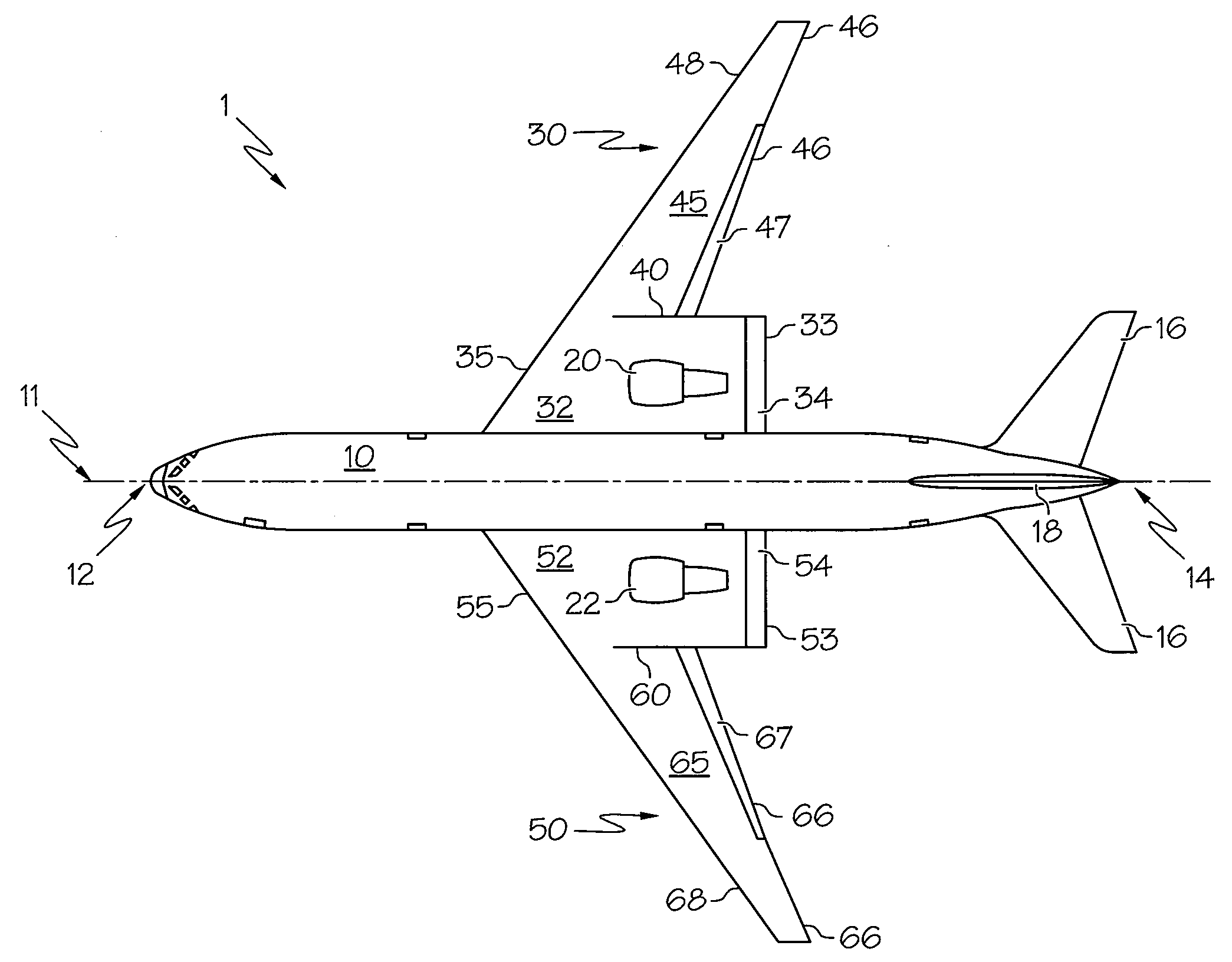
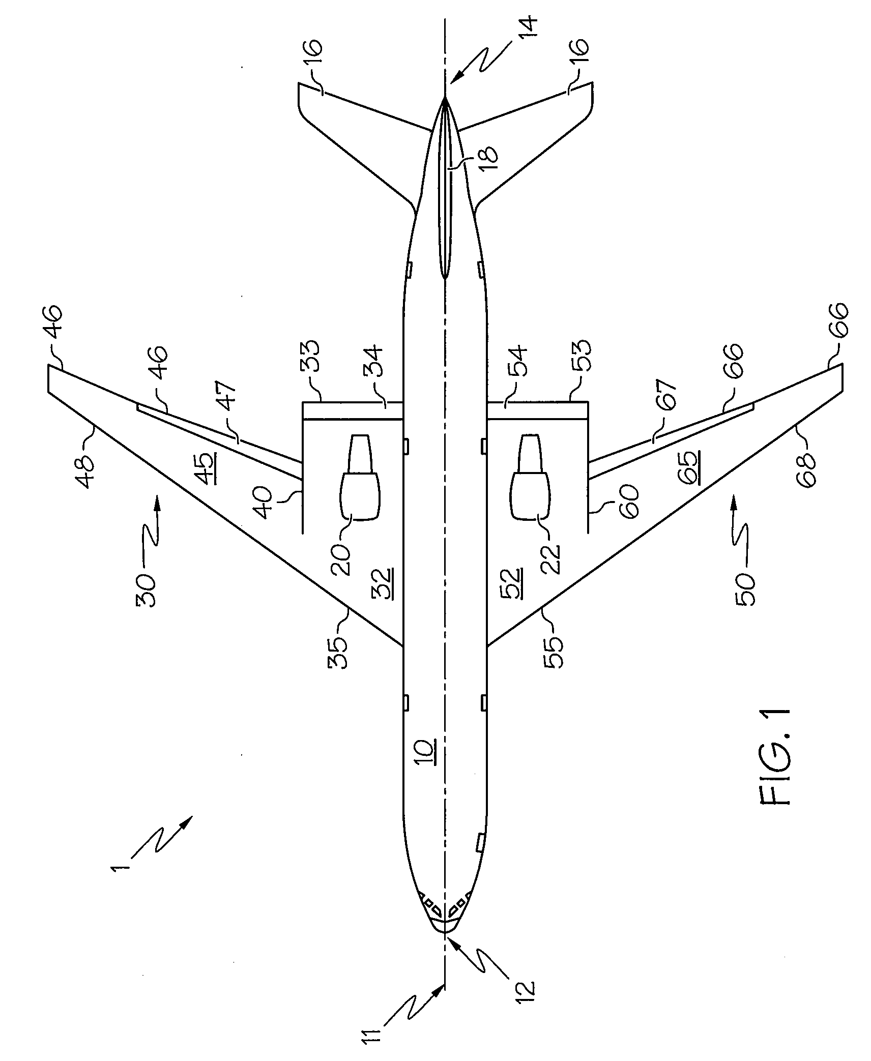
[0041]Referring to the drawings, FIG. 1 illustrates a top plan view of an aircraft 1 configured in accordance with an exemplary embodiment of the present invention. Although FIG. 1 illustrates an aircraft 1 having a low-wing configuration, other embodiments of the present invention may be configured with a high-wing, shoulder-wing, or mid-wing configuration as illustrated, for example, in other figures described herein. Similarly, although the figures illustrated herein generally depict swept and ta...


PUM


Abstract

Embodiments of the invention provide an aircraft configuration that provides for increased engine noise shielding for community noise reduction, while still providing desirable aerodynamic attributes such as good spanwise lift distributions and good structural integration without excessive wing surface area. Specifically, the aircraft is configured to have a longer-chord inboard wing portion and a shorter-chord outboard wing portion. The aircraft engines are positioned in major part over the longer-chord inboard wing portions such that communities below the wing are at least partially shielded by the inboard wing portion from the engine noise. Embodiments of the invention also strategically position fowler flaps or other chord-increasing devices in the region of the wing proximate the engine. Since the fowler motion increases the effective chord of the wing as the flaps are extended, the flaps may be deployed to increase the shielding characteristics of the wing.

Description

FIELD[0001]This invention relates to the field of aircraft design, and more particularly embodiments of the invention relate generally to an aircraft having a wing specifically configured to shield engine noise from surrounding communities.BACKGROUND[0002]Aircraft engines generate significant sound during operation. Excessive engine sound is generally undesirable since excessive sound may disturb surrounding communities.[0003]Conventional subsonic civil aircraft designs commonly feature engines placed underneath the aircraft's wings. The sound pressure level produced by the engines, herein generally referred to as “engine noise,” and particularly the engine noise generated during takeoff and landing, travels largely unabated to surrounding communities. For under-wing engine installations this noise is amplified by the lower surface of the wing because the portion of the sound produced by the engines that would otherwise radiate upward is reflected downward off of the lower surface o...

Claims


Application Information

Patent Timeline
Patent Type & Authority Applications(United States)
IPC IPC(8): B64C3/10B64D27/00
CPCB64C3/10B64C3/16B64C9/18B64C9/24B64C39/04Y02T50/44B64D27/18B64D27/20B64D33/06Y02T50/12Y02T50/32B64D27/12Y02T50/10Y02T50/30Y02T50/40
Inventor SANKRITHI, MITHRA M.K.V.PAISLEY, DAVID J.MOORE, MATTHEW D.
Owner THE BOEING CO
Why Eureka
Try Eureka