Tailless aircraft

A technology of aircraft and wings, applied in the field of controlling aircraft during flight

Active Publication Date: 2019-11-08
UNIVERSITY OF PRETORIA
View PDF10 Cites 0 Cited by
  • Summary
  • Abstract
  • Description
  • Claims
  • Application Information

AI Technical Summary

Problems solved by technology

[0006] The inventors realized that current state of the art aircraft do not fully achieve any of these three goals, therefore, in order to achieve a given flight goal, the aircraft is flying More energy than physically necessary is consumed during

Method used


Image

  • Tailless aircraft
  • Tailless aircraft
  • Tailless aircraft

Examples


Embodiment Construction

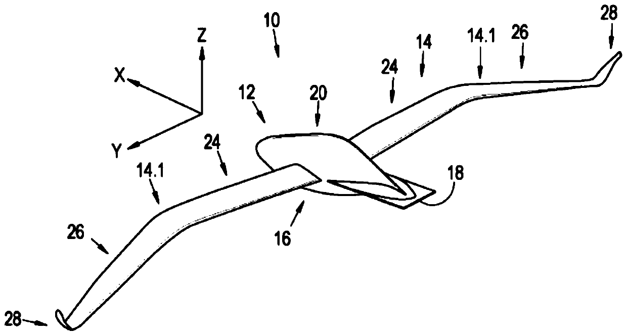
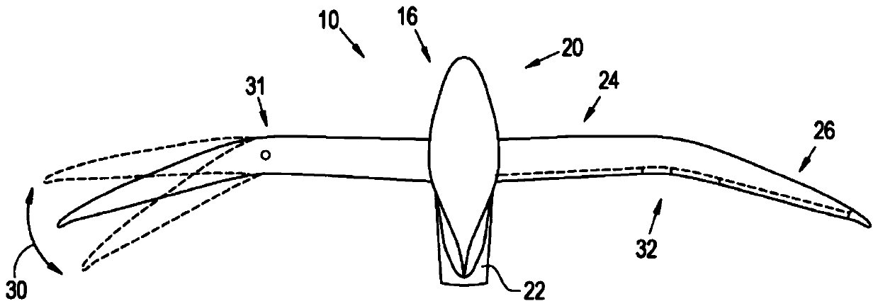
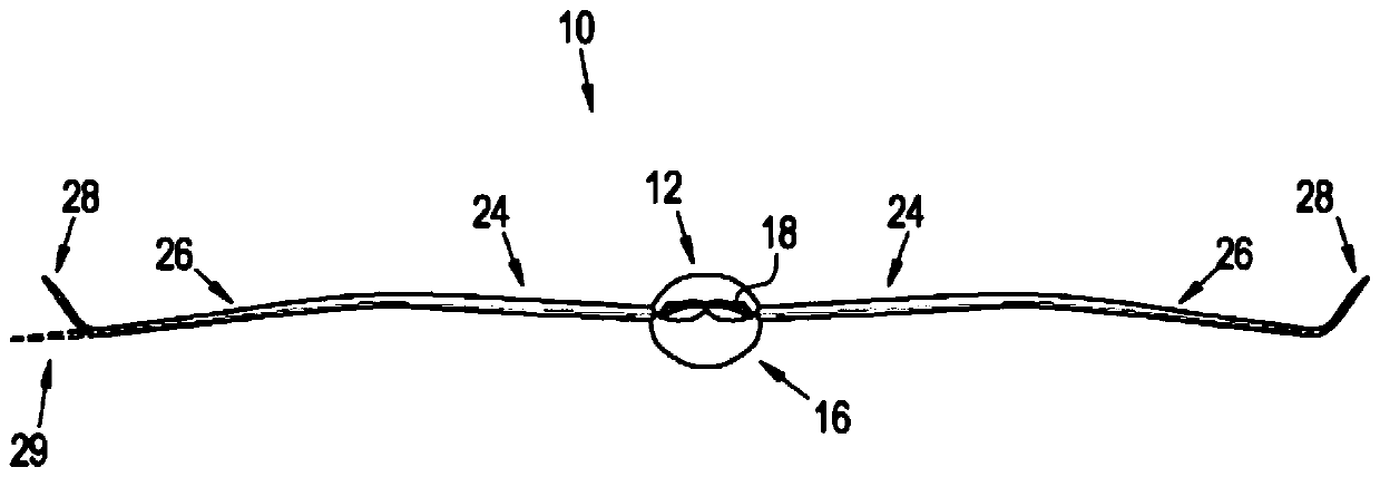
[0050]In the figures, reference numeral 10 generally refers to an aircraft according to the invention. Aircraft 10 includes a tailless fuselage, generally indicated by reference numeral 12 , and a wing 14 having two sides 14 . 1 connected to fuselage 12 and extending laterally from opposite sides of fuselage 12 .

[0051] Fuselage 12 includes an airframe generally indicated by reference numeral 16 , terminating in a transverse trailing edge 18 . In particular, the airframe 16 includes a hollow, bulbous main portion generally indicated by the reference numeral 20 and flaps 22 projecting rearwardly from the main portion 20 and forming the trailing edge 18 . relative to the attached figure 1 The vertical X, Y and Z axes shown in , when the aircraft 10 is intended to fly in the direction of the X-axis, the trailing edge 18 generally extends laterally in the direction of the Y-axis, ie, generally perpendicular to the direction of flight X. The position of the flap 22 relative to ...


PUM


Abstract

The invention relates to an aircraft having a tailless fuselage. The fuselage has a body which includes a transverse trailing edge. The aircraft further includes a wing having two sides which protrudefrom opposite sides of the fuselage. The body typically has a fineness ratio of between 3 and 7. Each side of the wing has an inner section having a first dihedral angle and an outer section having asecond dihedral angle, the second dihedral angle being less than the first dihedral angle. At least part of the outer section is typically swept back. The configuration of the aircraft provides it with improved flight efficiency.

Description

technical field [0001] The invention relates to an aircraft. The invention also relates to a method of controlling an aircraft in flight. Background technique [0002] All energy of flight is transferred from the flying body to the surrounding viscous medium through which the flying body moves, as the shear and pressure interactions between the flying body and the viscous medium change the momentum and the temperature of the medium. For good flight economics, it is in the interest of any operator of any flying body to transfer only a minimum amount of energy to the surrounding medium. Therefore, for efficiency, some design criteria that should be minimized simultaneously during the flight body design process include: [0003] Flying bodies should be minimized according to their lift requirements; [0004] Flying bodies should minimize the transfer of momentum through shear and pressure to the surrounding viscous medium; and [0005] A flying body should release the minim...

Claims


Application Information

Patent Timeline
Patent Type & Authority Applications(China)
IPC IPC(8): B64C9/06B64C17/02B64C17/10B64C39/10
CPCB64C9/06B64C17/02B64C17/10B64C39/10Y02T50/30B64C3/00B64U10/25
Inventor R·J·胡伊森
Owner UNIVERSITY OF PRETORIA
Why Eureka
Try Eureka