Wind turbine system for satisfying low-voltage ride through requirement

a technology of wind turbines and rotors, applied in the direction of rotors, electric generator control, vessel construction, etc., can solve the problems of excessive increase in the revolution speed of the turbine rotor, inability to continue to operate such-structured wind turbine systems, and undesirable in terms of safety. , to achieve the effect of reducing maintenan

Active Publication Date: 2009-03-05
MITSUBISHI HEAVY IND LTD
View PDF6 Cites 94 Cited by
  • Summary
  • Abstract
  • Description
  • Claims
  • Application Information

AI Technical Summary

Benefits of technology

[0010]Therefore, an object of the present invention is to provide a wind turbine system with the LVRT performance by using a mechanism that requires reduced maintenance.

Problems solved by technology

Most conventional wind turbine systems are designed so that controllers and other auxiliaries operate on electric power fed from the power grid; however, such-structured wind turbine systems can not continue to operate when the system voltage accidentally drops.
One important issue is that the system voltage drop may excessively reduce the load of the generator, resulting in an excessive increase in the revolution speed of the turbine rotor.
The excessive increase in the revolution speed is undesirable in itself in terms of safety.
Additionally, the excessive increase in the revolution speed may undesirably result in that an excessively large voltage is applied to a voltage converter connected with the generator.
In the technique disclosed in this patent, an uninterruptible power supply starts to feed electric power to necessary instruments (such as, a power converter, a turbine controller, a blade pitch control system, and a crowbar circuit), when the system voltage drop is detected; the uninterruptible power supply does not feed electric power to unnecessary instruments.
One issue of using a UPS is that the UPS requires lots of maintenance.
This undesirably increases the labor and cost needed for the maintenance of the wind turbine system.
This patent application, however, does not disclose a technique for dealing with an accidental system voltage drop.

Method used


Image

  • Wind turbine system for satisfying low-voltage ride through requirement
  • Wind turbine system for satisfying low-voltage ride through requirement
  • Wind turbine system for satisfying low-voltage ride through requirement

Examples


Embodiment Construction

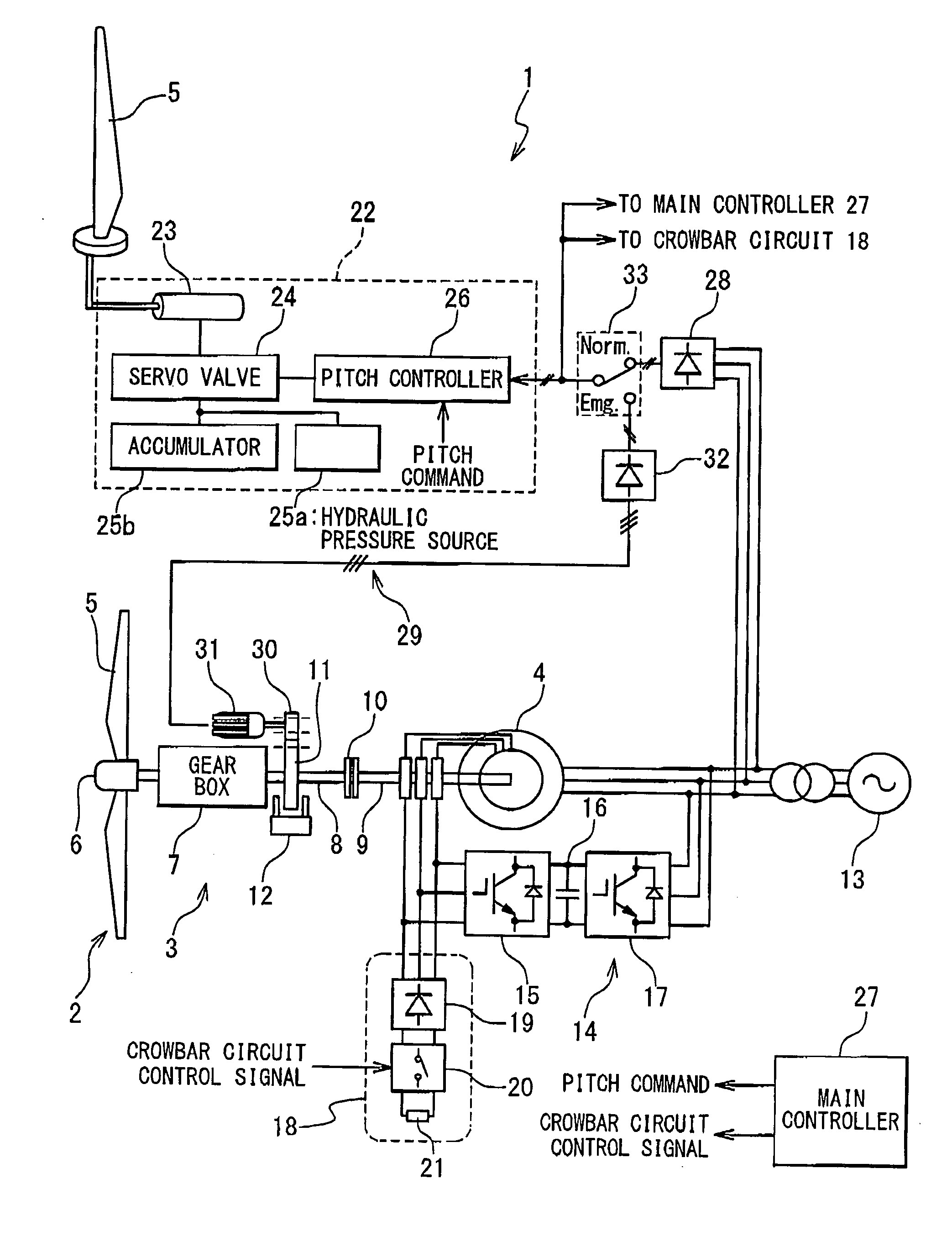
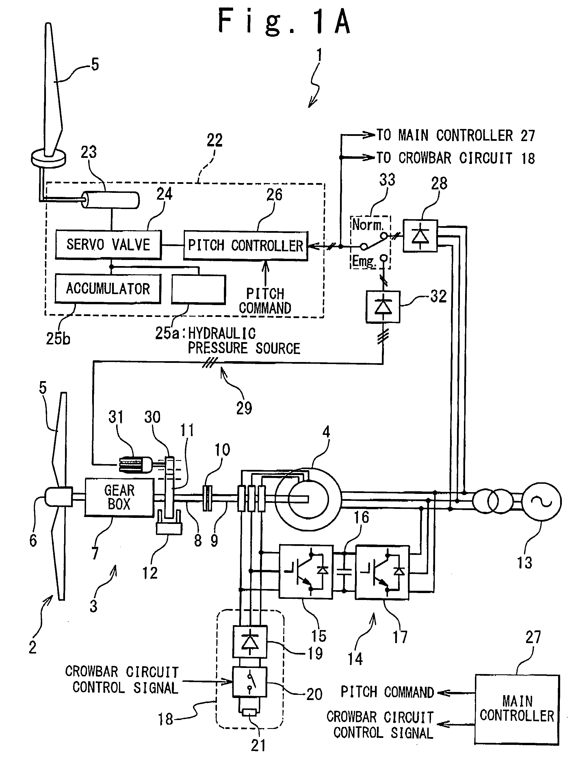
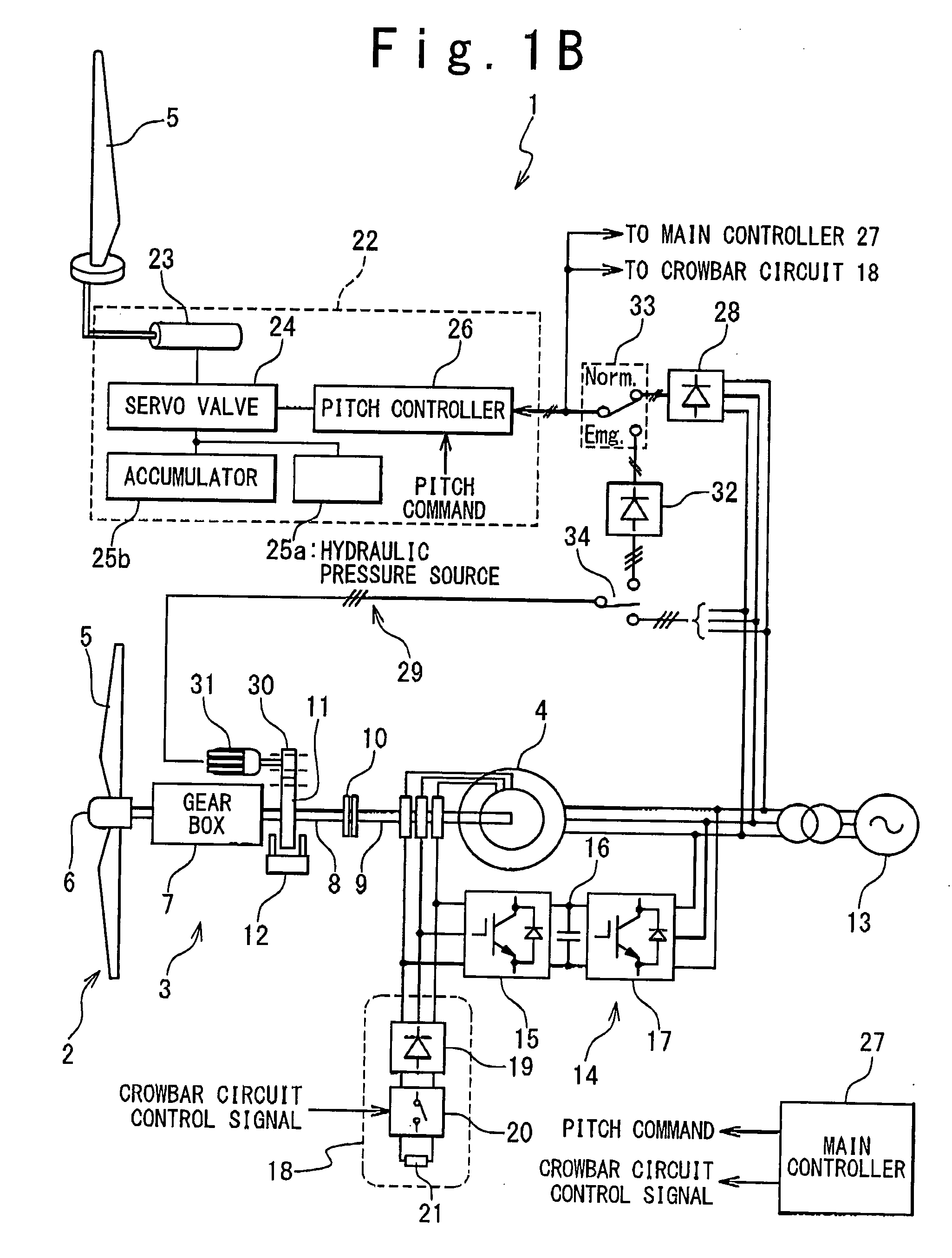
[0033]FIG. 1 is a block diagram illustrating the structure of a wind turbine system 1 in one embodiment of the present invention. The wind turbine system 1 is provided with a wind turbine rotor 2, a drive train 3, and a wound-rotor induction generator 4. The wind turbine rotor 2 is mechanically coupled with the rotor of the wound-rotor induction generator 4 through the drive train 3. The rotation of the wind turbine rotor 2 is transmitted to the wound-rotor induction generator 4 through the drive train 3 to thereby drive the wound-rotor induction generator 4.

[0034]The wind turbine rotor 2 is provided with blades 5 and a hub 6 that supports the blades 5. The blades 5 are supported so that the pitch angle thereof is variable.

[0035]The drive train 3 is provided with a gear box 7, a wind turbine shaft B, a generator shaft 9 and a coupling mechanism 10. The hub 6 of the wind turbine rotor 2 is mechanically connected with the wind turbine shaft 8 through the gear box 7, and the wind turbi...


PUM


Abstract

A wind turbine system is provided with a wind turbine rotor, a pitch control mechanism, and an emergency power supply mechanism. The wind turbine rotor includes a blade having a variable pitch angle. The pitch control mechanism drives the blade to control the pitch angle. The emergency power supply mechanism generates electric power from rotation of the wind turbine rotor and feeds the electric power to the pitch control mechanism, in response to occurrence of an accidental drop of a system voltage of a power grid.

Description

BACKGROUND OF THE INVENTION[0001]1. Field of the Invention[0002]The present invention relates to a wind turbine system, particularly to a technique for dealing with accidental drop of the system voltage in a power system.[0003]2. Description of the Related Art[0004]Recent wind turbine systems are required to feed electric power to the power grid with improved stability and higher reliability. One important requirement is to satisfy low-voltage ride through (LVRT) requirement which requires that a wind turbine power system must remain connected to the power grid when the system voltage suddenly drops resulting from an accident in the power grid. Most conventional wind turbine systems are designed so that controllers and other auxiliaries operate on electric power fed from the power grid; however, such-structured wind turbine systems can not continue to operate when the system voltage accidentally drops. One important issue is that the system voltage drop may excessively reduce the lo...

Claims


Application Information

Patent Timeline
Patent Type & Authority Applications(United States)
IPC IPC(8): F03D7/00
CPCF03D7/0224F03D9/003Y02E10/723F05B2270/10711F05B2270/107F03D15/10F03D9/255Y02E10/72
Inventor ARINAGA, SHINJIMATSUSHITA, TAKATOSHIWAKASA, TSUYOSHI
Owner MITSUBISHI HEAVY IND LTD
Why Eureka
Try Eureka