

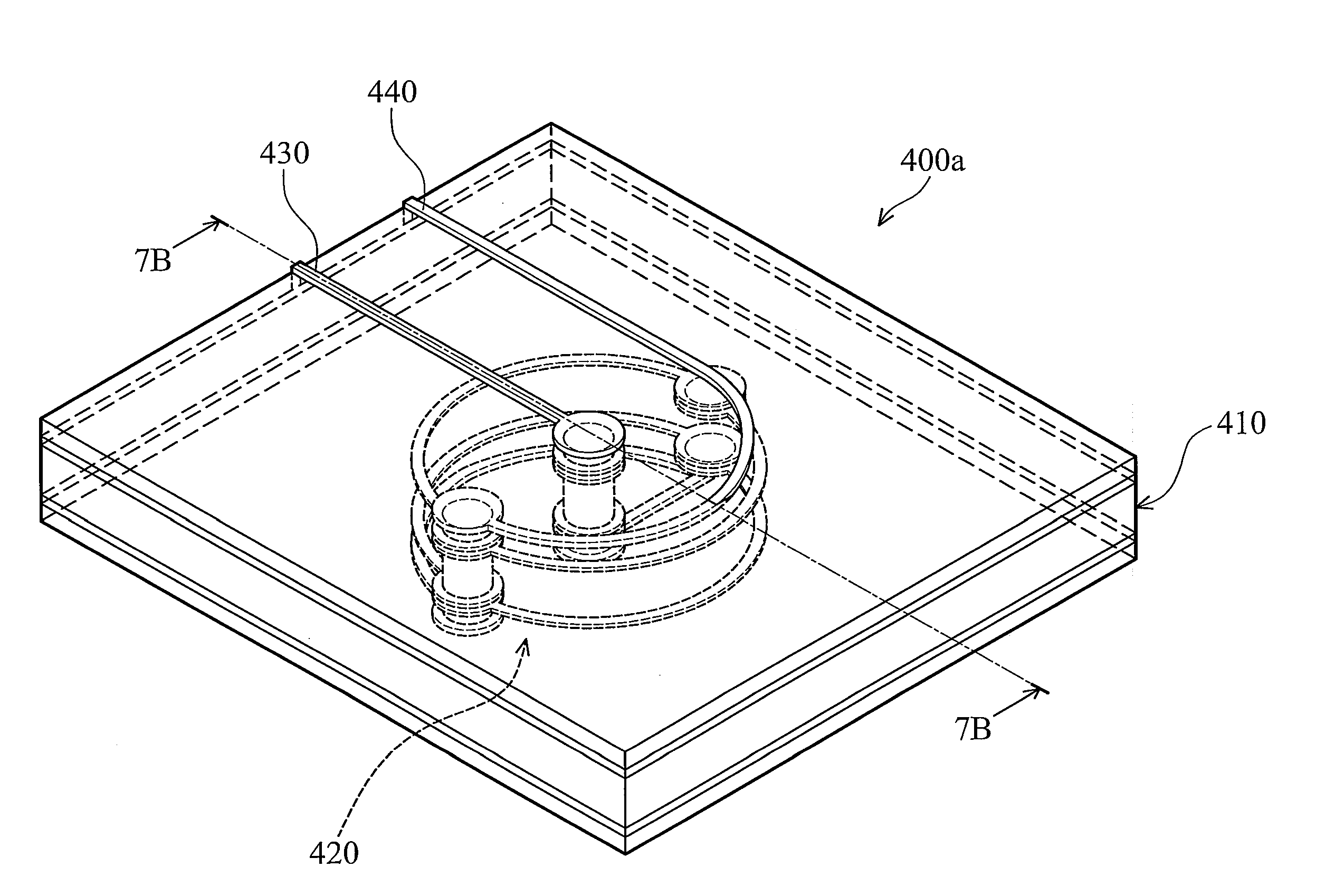
Suspension inductor devices
a technology of suspension inductor and inductor, which is applied in the direction of inductance, transformer/inductance coil/winding/connection, continuous variable inductance/transformer, etc., can solve the problems of demodulation failure of communication system, undesirable signal loss, and the operation of active circuit cannot work within the typical working frequency range, so as to achieve the effect of reducing the circuit layout area of suspension inductor devices and high inductance and quality factor characteristics
- Summary
- Abstract
- Description
- Claims
- Application Information
AI Technical Summary
Benefits of technology
Problems solved by technology
Method used
Image

Examples
Embodiment Construction
[0040]A detailed description is given in the following embodiments with reference to the accompanying drawings.
[0041]It is to be understood that the following disclosure provides many different embodiments, or examples, for implementing different features of various embodiments. Specific examples of components and arrangements are described below to simplify the present disclosure. These are merely examples and are not intended to be limiting. In addition, the present disclosure may repeat reference numerals and / or letters in the various examples. This repetition is for the purpose of simplicity and clarity and does not in itself indicate a relationship between the various embodiments and / or configurations discussed. Moreover, the formation of a first feature over or on a second feature in the description that follows may include embodiments in which the first and second features are formed in direct contact or not in direct contact.
[0042]Main features and key aspects of a stereogra...
PUM
 Abstract
Description
Claims
Application Information