Technique for Cooling a Device

Inactive Publication Date: 2009-03-05
IBM CORP
View PDF6 Cites 35 Cited by
  • Summary
  • Abstract
  • Description
  • Claims
  • Application Information

AI Technical Summary

Benefits of technology

[0002]A rack-mounted computer system allowing a plurality of high-performance electronic devices to be effectively accommodated therein is widely used. Due to the high performance, an amount of heat generated by such a system tends to be large, and therefore in order to improve the cooling effect by air, such a system comes with a rapidly-rotating fan. As a resu

Problems solved by technology

As a result, operation sound (noise) therefrom is high.
However, a room dedicated to accommodate such a system cannot be always secured in such a case as well.

Method used


Image

  • Technique for Cooling a Device
  • Technique for Cooling a Device
  • Technique for Cooling a Device

Examples


Embodiment Construction

[0012]Although the following describes the present invention by way of embodiments, the following embodiments do not limit the invention according to the claims of the present invention, and all of the features described in the embodiments are not always essential to solving means of the present invention.

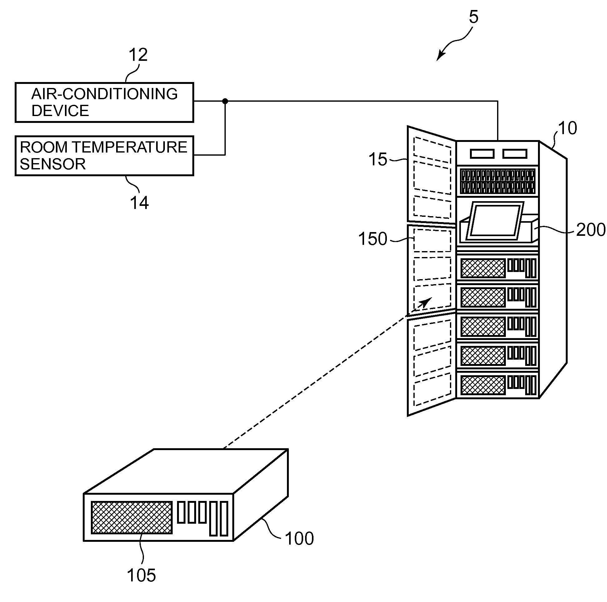
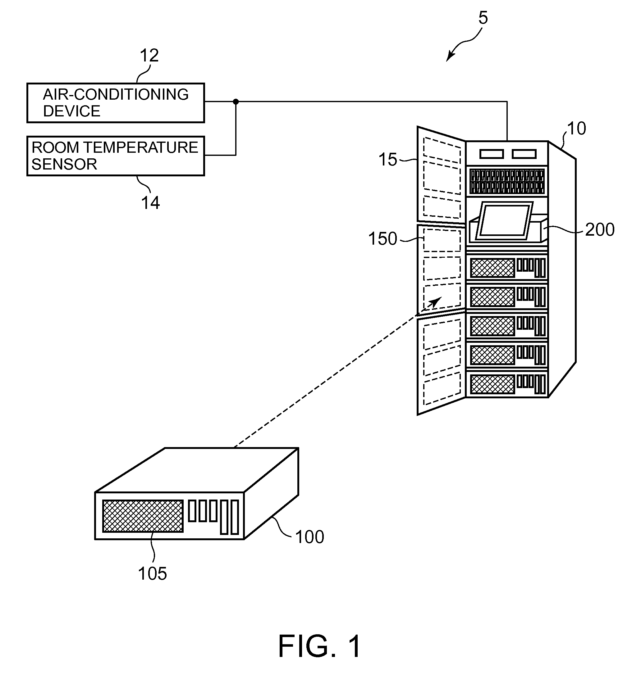
[0013]FIG. 1 shows the overall configuration of a cooling system 5 according to the present embodiment. The cooling system 5 includes a computer system 10, an air-conditioning device 12 and a room temperature sensor 14. The computer system 10 is a rack-mounted system allowing a plurality of devices to be stacked and incorporated therein. At least one of the devices incorporated in the computer system 10 is a heat-generating device due to sophisticated computations such as a computer 100. Therefore, the computer 100 includes an air inlet 105 at a front face thereof, for example, for taking in outside air for cooling the computer 100. The air taken in from the outside is used for coo...


PUM


Abstract

A cooling system that promotes cooling of a device including a heat source therein is provided, the cooling system includes: a cooling unit that absorbs, upstream from the heat source, heat from intake air that the device takes in from an outside to cool the heat source and dissipates the heat to an outside of a flow path of the intake air; and a fluid control unit that lets fluid flow toward the cooling unit so as to discharge the heat absorbed by the cooling unit from the intake air to an outside of the cooling unit.

Description

FIELD OF THE INVENTION [0001]The present invention relates to a technique for cooling a heat-generating device. More particularly, the present invention relates to a technique for cooling a heat-generating device by fluid.SUMMARY OF THE INVENTION [0002]A rack-mounted computer system allowing a plurality of high-performance electronic devices to be effectively accommodated therein is widely used. Due to the high performance, an amount of heat generated by such a system tends to be large, and therefore in order to improve the cooling effect by air, such a system comes with a rapidly-rotating fan. As a result, operation sound (noise) therefrom is high. Further, in order to secure high reliability and processing power, such a system is desirably to operate under climate controlled conditions at a low temperature. Thus, in many cases, such a system is installed for operation in a room dedicated to accommodate a computer system that is isolated from a general office.[0003]In recent years,...

Claims


Application Information

Patent Timeline
IPC IPC(8): H05K7/20F28D15/00
CPCH05K7/20572H05K7/20563Y10S257/93
Inventor KAKIKAWA, KOHICHIMATSUI, YOHICHITAKENOSHITA, HIROYUKI
Owner IBM CORP
Why Eureka
Try Eureka