Single-phase to three-phase converter

a converter and single-phase technology, applied in the direction of power conversion systems, ac-ac conversion, electrical apparatus, etc., can solve the problems of reducing the total manufacturing cost of the converter, and reducing the overall manufacturing cos

Inactive Publication Date: 2009-03-05
ABB OY
View PDF7 Cites 46 Cited by
  • Summary
  • Abstract
  • Description
  • Claims
  • Application Information

AI Technical Summary

Problems solved by technology

The structure of FIG. 1 has a large inductor and six controllable switches, which makes the costs relating to components rather high.
Further the structures shown in FIGS. 1 and 2 are designed for only one mains voltage, and doesn't therefore provide for a universal structure.
Thus the problem relating to the prior art single-phase to three-phase converters is the number of controllable components and the large inductor required, which both contribute greatly to the total manufacturing costs.

Method used


Image

  • Single-phase to three-phase converter
  • Single-phase to three-phase converter
  • Single-phase to three-phase converter

Examples


Embodiment Construction

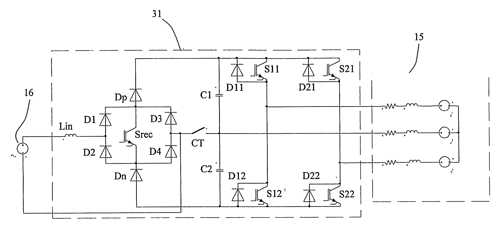
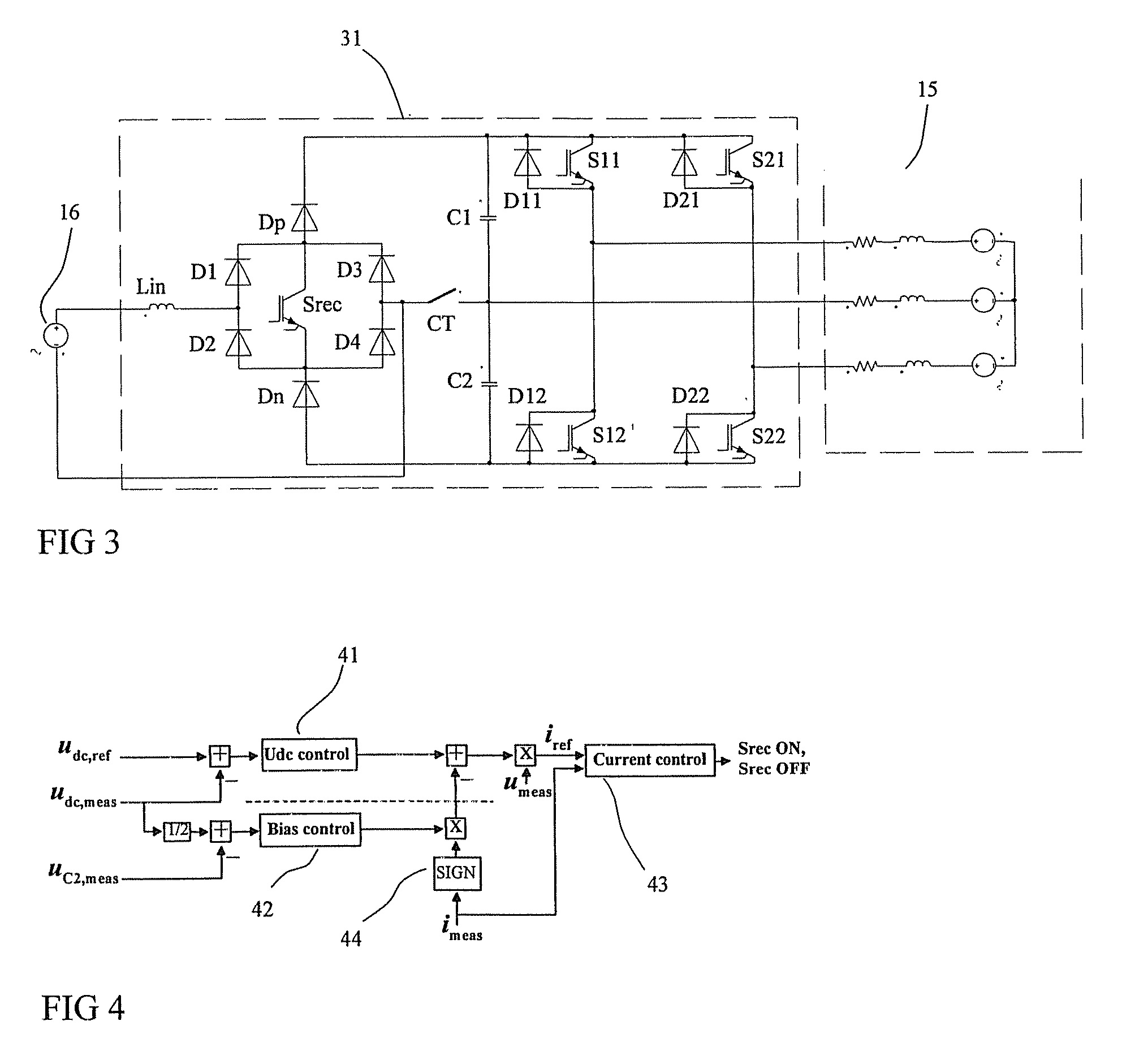
[0022]FIG. 3 shows the structure of a single-phase to three-phase converter 31 according to the present invention. In this structure the rectifier stage is formed of a diode bridge D1, D2, D3, D4 having an input and an output. The input of the diode bridge is formed between diodes D1, D2 and diodes D3, D4, and the output is formed between diodes D1, D3 and diodes D2, D4. An inductor Lin is connected to the positive input of the diode bridge.

[0023]A controllable switch Srec is connected between the output terminals of the diode bridge, and a blocking diode Dp is connected to the positive output of the diode bridge between said positive output and the positive rail of a DC link. Similarly another blocking diode is connected between the negative output of the diode bridge and the negative rail of the DC link. The polarities of the blocking diodes are such that a current can flow from the positive output of the diode bridge to the positive rail of the DC link and from the negative rail ...


PUM


Abstract

Single-phase to three-phase converter comprising a rectifier stage, a DC link and an inverter stage, wherein the rectifier comprises a filter choke, one controllable switch for power factor correction, rectifying diodes arranged in a diode bridge configuration having input terminals and output terminals, the controllable switch being connected to the output terminals of the diode bridge, an upper blocking diode arranged between the positive output terminal of the diode bridge and the positive input of the DC link and a lower blocking diode arranged between the negative output terminal of the diode bridge and the negative input of the DC link, the DC link comprises a capacitor bank connected between the DC link, which capacitor bank has a center point. The inverter stage comprises three phase outputs, two of which are formed with a series connections of controllable switches arranged between the DC link for switching either positive voltage or negative voltage of the DC link to the phase outputs, and one phase output is formed of the voltage of the center point of the capacitor bank, and in that the center point of the capacitor bank is configured to be optionally connected to the neutral line of the single-phase AC input by using a connection switch element providing thereby doubled voltage to the DC link.

Description

FIELD OF THE INVENTION[0001]The present invention relates to a converter for converting electrical energy, and more particularly to a converter that converts electrical energy from a single-phase supply to a three-phase load.BACKGROUND OF THE INVENTION[0002]A single-phase AC voltage is used commonly for powering three-phase loads by using a converter which converts the input single-phase supply to a three-phase output voltage. The basic structure of a converter includes an input bridge, a DC link and an inverter stage. Input bridge, such as a diode rectifier, rectifies inputted AC voltage. Input bridge may also contain an inductor for suppressing current harmonics and a power factor correction circuit.[0003]The rectified voltage is fed from the rectifier to the DC link. This DC link, also called as intermediate voltage circuit, contains a capacitor or a capacitor bank for storing and smoothing the rectified voltage.[0004]The inverter stage of the converter is coupled to the DC link ...

Claims


Application Information

Patent Timeline
Patent Type & Authority Applications(United States)
IPC IPC(8): H02M5/45
CPCH02M7/48H02M5/458
Inventor VIITANEN, TERONIEMI, ERKKI
Owner ABB OY
Why Eureka
Try Eureka