Image blur correction device, lens barrel and imaging apparatus

Inactive Publication Date: 2009-03-05
SONY CORP
View PDF2 Cites 48 Cited by
  • Summary
  • Abstract
  • Description
  • Claims
  • Application Information

AI Technical Summary

Benefits of technology

[0010]Japanese Unexamined Patent Application Publication No. 3-188430 discloses another example of an image blur correction device of the related art. Japanese Unexamined Patent Application Publication No. 3-188430 discloses a camera image blur suppression device detecting vibration (shake) at a frequency of about 1 Hz to 12 Hz generated in equipment such as a camera as information to suppress an image blur. The camera image blur suppression device disclosed in Japanese Unexamined Patent Application Publication No. 3-188430 (hereinafter referred to as “second related art example”) “determines a correction amount for eccentricity of an optical axis necessary for suppressing an image blur on an image surface based on detected information on vibration generated in a lens barrel and controls movement of a correction optical system floatingly supported to be movable in a diameter direction of the lens barrel according to the correction amount. The floatingly-supported correction optical system includes a first holding frame supporting the correction optical system to be movable in a first direction determined in a plane perpendicular to the optical axis but restraining movement of the correction optical system in other directions; and a second holding frame supporting the first holding frame to be movable in a second direction differing from the first direction in the plane but restraining movement thereof in other directions, the second holding frame fixed to the lens barrel.”
[0011]According to the camera image blur suppression device disclosed in Japanese Unexamined Patent Application Publication No. 3-188430 having such a configuration, it is expected that “a problem of defocusing may not occur during suppression of an image blur, and the correction optical mechanism may be formed to have a reduced dimension in an optical axis direction, enabling a camera to be reduced in size.”
[0012]However, the first or second related art example includes four guide shafts in total as essential components, specifically, a pair of pitch shafts (guide shafts) slidably supporting a fixing frame having a correction lens; and a pair of yaw shafts (guide shafts) slidably supporting a first holding frame. Therefore, it may be necessary to ensure a space for placing the four shafts, thus increasing an image blur correction

Problems solved by technology

However, no matter how much the performance of lenses, imaging devices or the like is improved, a high resolution screen blurs and thus a captured image blurs when hands supporting a camera (imaging apparatus) tremble or shake.
Therefore, some relatively expensive cameras have an image blur correction device mounted and correcting an image blur caused by shake or the like during photographing.
However, image blur correction devices of the related art are relatively large.
Therefore, when the image blur co

Method used


Image

  • Image blur correction device, lens barrel and imaging apparatus
  • Image blur correction device, lens barrel and imaging apparatus
  • Image blur correction device, lens barrel and imaging apparatus

Examples


Example

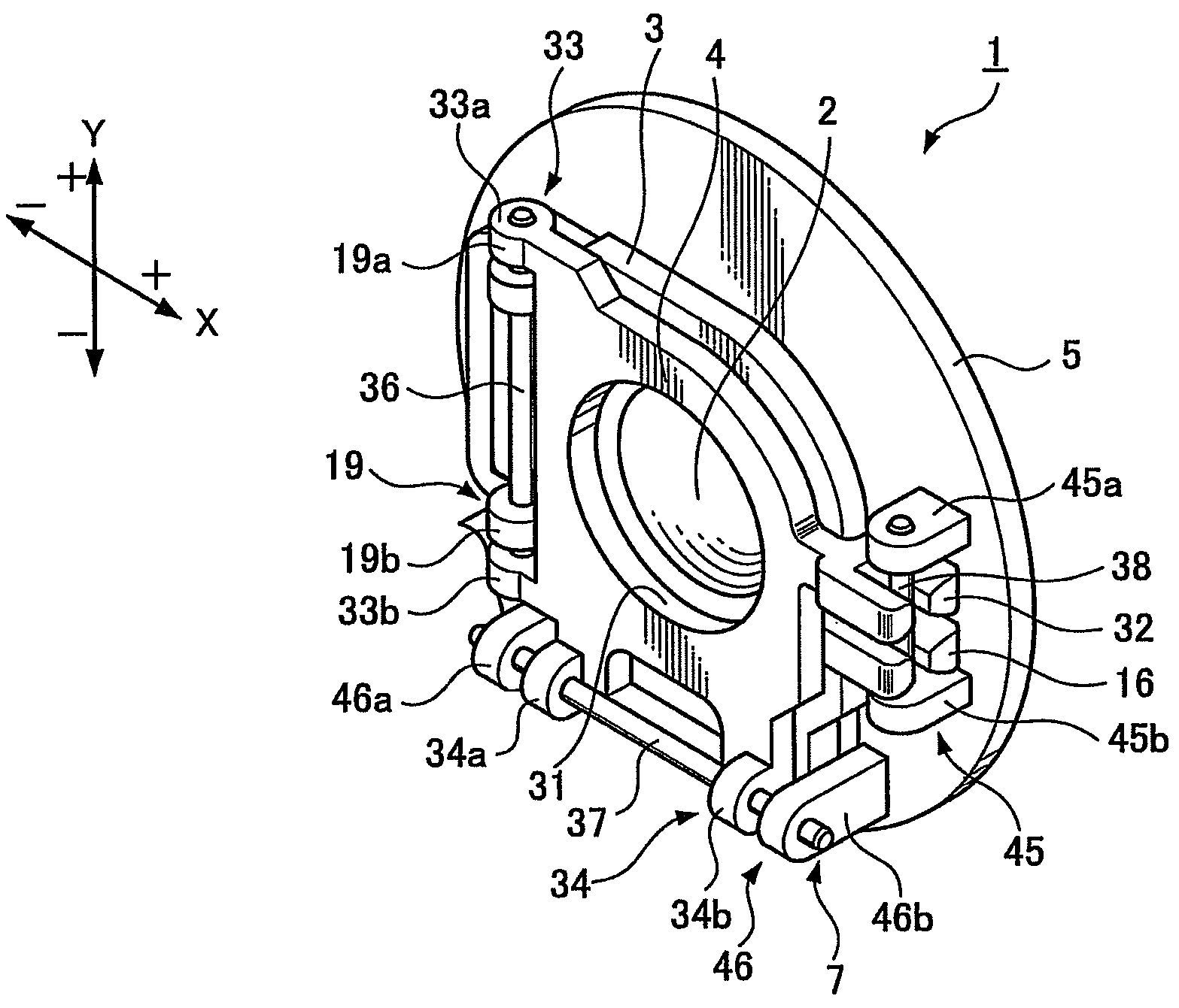
[0054]An image blur correction device and a lens barrel and an imaging apparatus including the image blur correction device are realized with a simplified structure, where the image blur correction device includes a guide mechanism having at least one guide shaft guiding both a first movable frame and a second movable frame, making it possible to reduce the number of guide shafts and reduce the whole device in size.

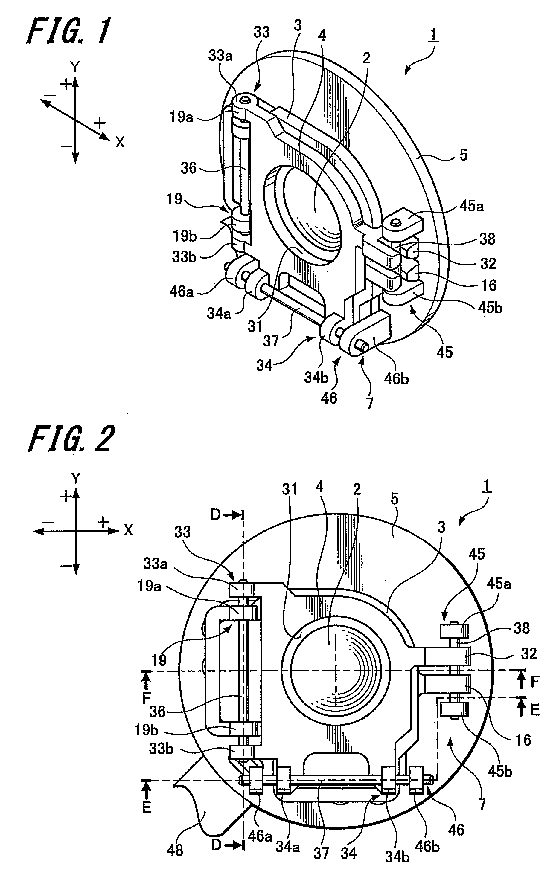
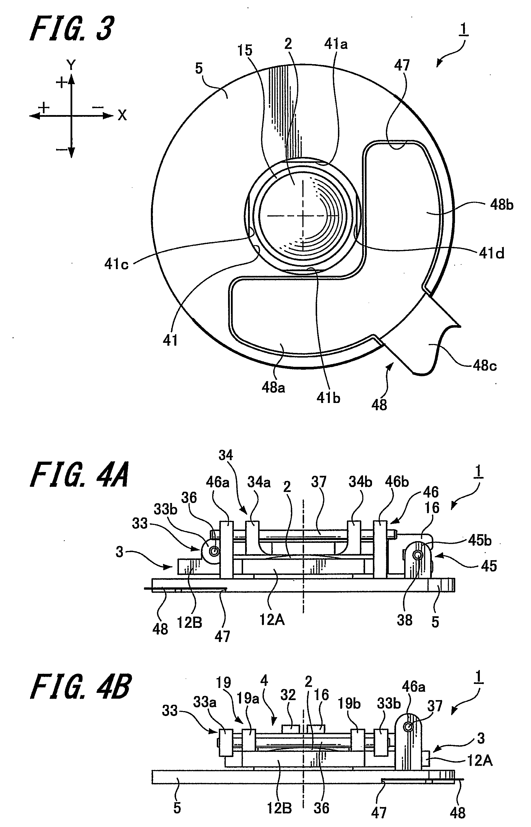
[0055]Embodiments of the present invention will be described below with reference to the attached drawings. FIGS. 1 to 36 describe examples of embodiments of the present invention. Specifically, FIG. 1 is a perspective view showing a first example of an image blur correction device according to an embodiment of the present invention. FIG. 2 is a plan view of the same. FIG. 3 is a bottom view of the same. FIG. 4A is a front view of the same and FIG. 4B is a left side view of the same. FIG. 5A is a cross-sectional view of a part along a D-D line of the image blur correction...


PUM


Abstract

An image blur correction device is provided. The device includes a correction lens, a first movable frame, a second movable frame, a fixed base, a driving part and a guide mechanism. The correction lens is configured to correct an image blur in a lens system. The first movable frame holds the correction lens. The second movable frame supports the first movable frame to be movable in a first direction perpendicular to an optical axis of the lens system. The fixed base supports the second movable frame to be movable in a second direction perpendicular to the optical axis of the lens system and perpendicular to the first direction. The driving part moves the first movable frame in the first direction and moves the second movable frame in the second direction. The guide mechanism has at least one guide shaft guiding both the first movable frame and the second movable frame.

Description

CROSS REFERENCES TO RELATED APPLICATIONS[0001]The present invention contains subject matter related to Japanese Patent Application JP 2007-221706 filed in the Japanese Patent Office on Aug. 28, 2007, the entire contents of which being incorporated herein by reference.BACKGROUND OF THE INVENTION[0002]1. Field of the Invention[0003]The present invention relates to an image blur correction device correcting an image blur caused by vibration or the like during photographing, a lens barrel having the image blur correction device, and an imaging apparatus such as a digital still camera or video camera having the lens barrel.[0004]2. Description of the Related Art[0005]In recent years, performance of imaging apparatuses such as digital still cameras and video cameras has been remarkably improved, and thus still images and moving images may be easily captured by everyone with high image quality and high performance. Such improvement in performance of imaging apparatuses is largely due to im...

Claims


Application Information

Patent Timeline
IPC IPC(8): G03B17/00
CPCG03B5/00G02B27/646
Inventor TAKAHASHI, TATSUYUKI
Owner SONY CORP
Why Eureka
Try Eureka