Bicycle rear derailleur

a rear derailleur and bicycle technology, applied in mechanical devices, transportation and packaging, gearing, etc., can solve the problems of rear derailleur breaking, disengagement prevention part, jamming in teeth, etc., and achieve the effect of reducing the weight of the derailleur, reducing the position of the chain disengagement prevention part, and simplifying the support structure of the guide pulley and the chain guid

Inactive Publication Date: 2009-03-05
SHIMANO INC
View PDF4 Cites 12 Cited by
  • Summary
  • Abstract
  • Description
  • Claims
  • Application Information

AI Technical Summary

Benefits of technology

[0031]A bicycle rear derailleur in accordance with a tenth aspect of the present invention is a derailleur in accordance with any one of the first to ninth aspects, wherein the chain guide is configured as solely apply tension to a chain when the chain is mounted on the guide pulley and the tension pulley. With single tension rear derailleurs, it is more difficult to alleviate a jam in which the chain disengagement prevention part becomes jammed in the rear sprocket than in the case of a double tension rear derailleur because the chain is guided solely by the pivoting of the chain guide.
[0032]A bicycle rear derailleur in accordance with an eleventh aspect of the present invention is a derailleur in accordance with any one of the first to tenth aspects, wherein the mounting member includes a bracket configured to be fixed to the frame, and a base member pivotally connected to the bracket for pivoting about a second axis. With this aspect of the present invention, the position of the chain disengagement prevention part can be changed by changing the shape of the bracket alone. Thus, if the rear derailleur is to be used on a special frame that causes the chain disengagement prevention part to be in a position where it can easily become jammed in the sprocket, then the chain disengagement prevention part can be arranged in a position where it will not easily become jammed in the sprocket by merely changing the shape of the bracket as appropriate.
[0033]A bicycle rear derailleur in accordance with a twelfth aspect of the present invention is a derailleur in accordance with any one of the first to eleventh aspects, wherein the guide pulley has a center rotational axis that coincides with the first axis. In this aspect of the present invention, the pivot center of the chain guide and the rotational center of the guide pulley are coincident with each other. As a result, the guide pulley and the chain guide can be supported on the movable member with the same member and the support structure of the guide pulley and the chain guide can be simplified.
[0034]A bicycle rear derailleur in accordance with a thirteenth aspect of the present invention is a derailleur in accordance with any one of the first to twelfth aspects, wherein the guide pulley and the tension pulley each have a tooth count of thirteen or smaller. With this aspect of the present invention, since both pulleys can be made to have smaller diameters, the weight of the derailleur can be reduced and contact of the tension pulley against the rear sprocket that could result from a larger pulley diameter can be prevented.
[0035]In this present invention, the chain disengagement prevention part is formed by folding an edge portion of the first or second plate member that is located on the side of the plate member that is closer to the mounting member. Consequently, when the chain guide is close to the rear sprocket, the chain disengagement prevention part is farther from the rear sprocket than it would be if it were formed by bending an edge portion of the first or second plate member that is located on the side of the plate member that is farther from the mounting member, i.e., the chain disengagement prevention part is in a position where it cannot easily become jammed in the teeth of the rear sprocket. Thus, the chain disengagement prevention part is less likely to become jammed in the teeth of the rear sprocket.
[0036]In another aspect of the present invention, the chain disengagement prevention part is arranged on the side of a contact line (tangent line) joining the two pulleys that is closer to the mounting member. As a result, the chain disengagement prevention part is arranged in a position separated from the rear sprocket where it cannot easily become jammed in the teeth of the rear sprocket. Thus, the chain disengagement prevention part is even less likely to become jammed in the teeth of the rear sprocket. Furthermore, since the chain disengagement prevention part is shaft-shaped, it will not easily become jammed even if it does contact in-between the teeth of the rear sprocket. Consequently, even when the chain guide is in the most forwardly pivoted position, the chain disengagement prevention part does not easily become jammed in the rear sprocket.

Problems solved by technology

When this further rotation occurs, it is possible for the chain disengagement prevention part to enter in-between the teeth of the sprocket and become jammed in the teeth.
However, if the derailleur is a single tension type, then there is the possibility that the chain disengagement prevention part, i.e., the inside plate member, will moved forcefully by the sprocket and the rear derailleur will be broken.

Method used


Image

  • Bicycle rear derailleur
  • Bicycle rear derailleur
  • Bicycle rear derailleur

Examples


first embodiment

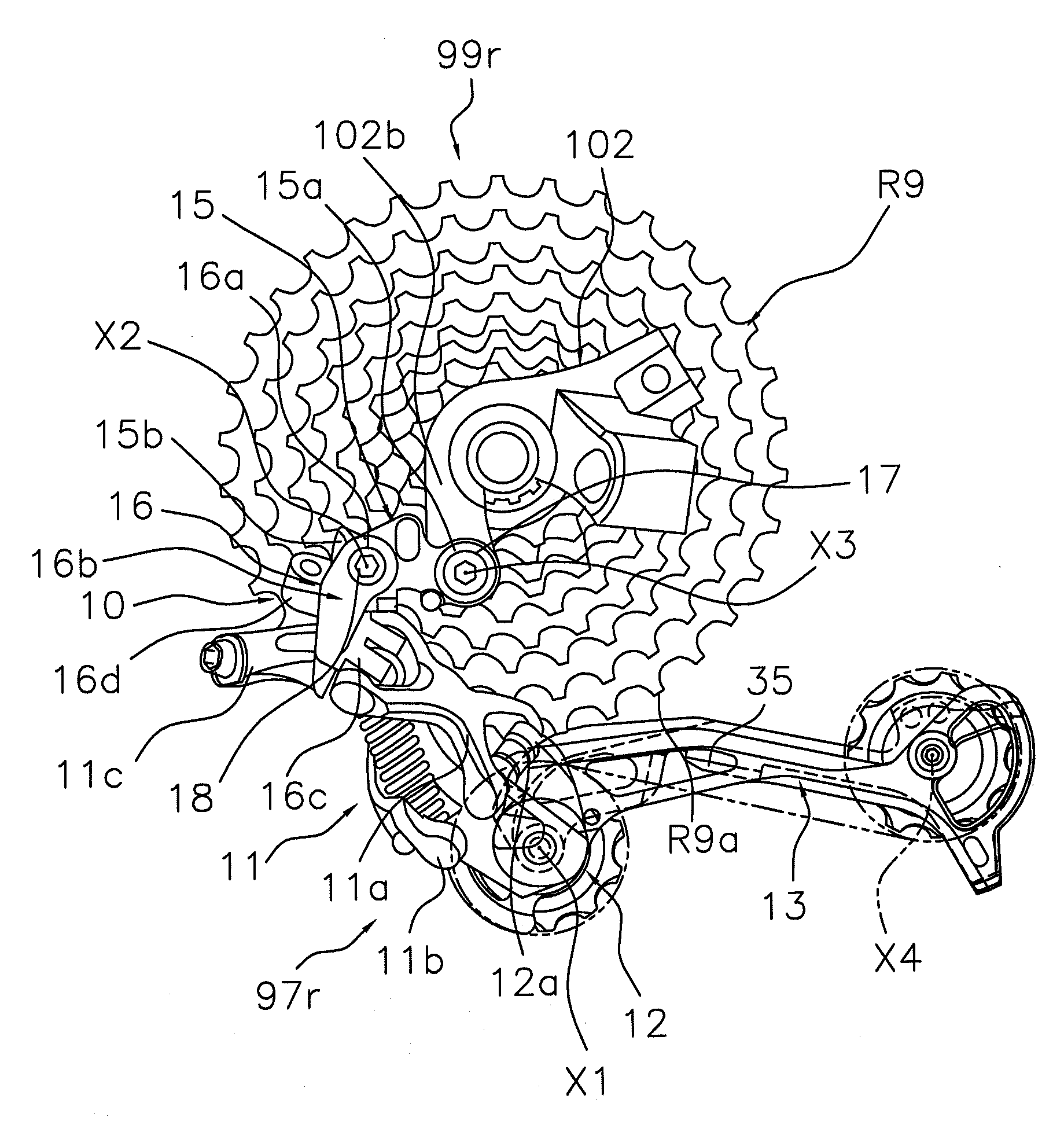
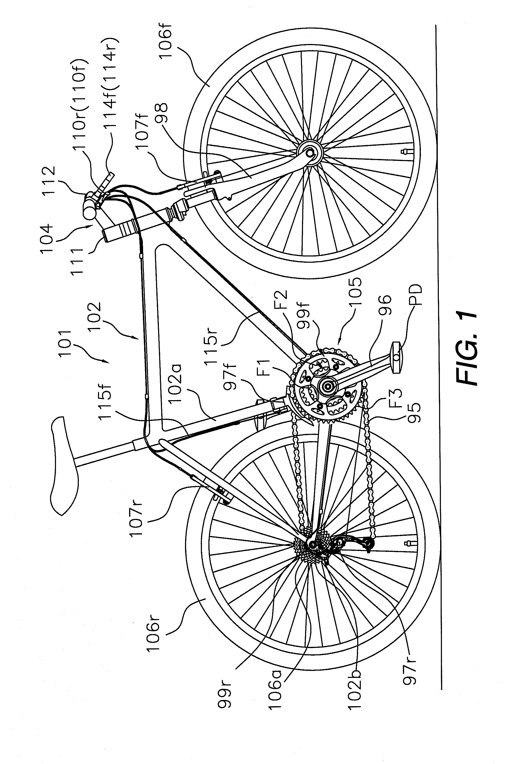
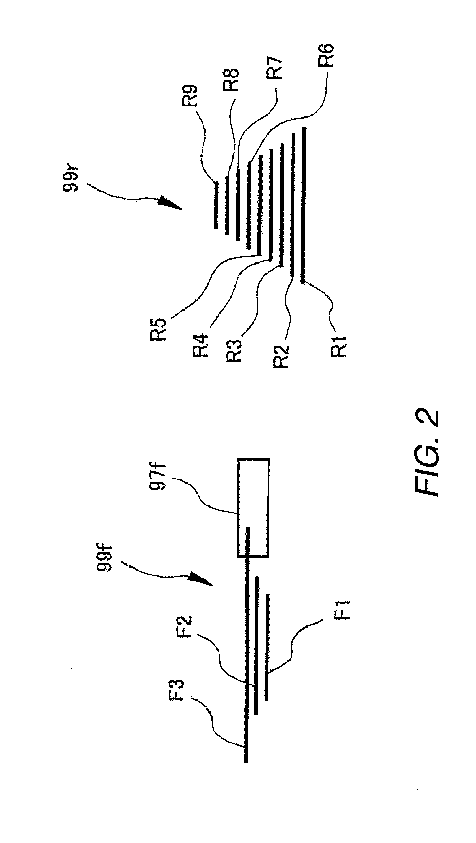
[0053]Referring initially to FIG. 1, a bicycle 101 is illustrated with a rear derailleur 97r in accordance with one embodiment of the present invention. In the illustrated embodiment, the bicycle 101 is a mountain bike for off-road use. The bicycle 101 basically includes a frame 102, a drive train (component) 105, front and rear wheels 106f and 106r, front and rear brake devices 107f and 107r, and a pair of (front and rear) gearshift operating parts or shifters 110f and 110r. The frame 102 has diamond shape. A front fork 98 is pivotally coupled to the frame 102 and a handlebar component 104 is fixedly attached to the front fork 98 to steer the bicycle 101. The drive train (component) 105 includes a chain 95, a crank set 96 to which a pair of pedals PD are mounted, front and rear derailleurs 97f and 97r, front and rear sprocket clusters 99f and 99r (i.e. a plurality of front chain rings and a rear sprocket cassette), and a freewheel (not shown) mounted between the rear sprocket clust...

second embodiment

[0082]Referring now to FIGS. 11 and 12, a pair of chain guides 213 and 313 will now be explained in accordance with a second embodiment. The chain guides 213 and 313 are used with the rear derailleur 97r by replacing the chain guide 13 with either the chain guide 213 or the chain guide 313. In view of the similarity between the first and second embodiments, the parts of the second embodiment that are identical to the parts of the first embodiment will be given the same reference numerals as the parts of the first embodiment. Moreover, the descriptions of the parts of the second embodiment that are identical to the parts of the first embodiment may be omitted for the sake of brevity.

[0083]While in the first embodiment the chain disengagement prevention part is formed by folding a portion of the inside plate member or the outside plate member, it is also acceptable for the chain drop preventing member to comprise, for example, a shaft-like member provided so as to protrude from one of...

third embodiment

[0090]Referring now to FIG. 13, a chain guide 413 will now be explained in accordance with a third embodiment. The chain guide 413 is used with the rear derailleur 97r of the first embodiment by replacing the chain guide 13 with the chain guide 413. In view of the similarity between the first and third embodiments, the parts of the third embodiment that are identical to the parts of the first embodiment will be given the same reference numerals as the parts of the first embodiment. Moreover, the descriptions of the parts of the third embodiment that are identical to the parts of the first embodiment may be omitted for the sake of brevity.

[0091]In a third embodiment, as shown in FIG. 13, the chain disengagement prevention part 435 of the chain guide 413 is arranged to be aligned with the contour of the chain 95 mounted across the two pulleys 22 and 23 and the chain disengagement prevention part 413 is entirely arranged on the side of the contact line CL that is closer to the mounting...


PUM


Abstract

A bicycle rear derailleur basically comprises a mounting member, a movable member, a connecting mechanism and a chain guide. The chain guide includes a first plate member, a second plate member, a guide pulley and a tension pulley, with at least one of the first and second plate members including a chain disengagement prevention part arranged between the guide pulley and the tension pulley. The chain disengagement prevention part is arranged to make it more difficult for a chain disengagement prevention part provided on a chain guide to become jammed in a sprocket.

Description

CROSS-REFERENCE TO RELATED APPLICATIONS[0001]This application claims priority under 35 U.S.C. § 119 to Japanese Patent Application No. 2007-226714, filed Aug. 31, 2007. The entire disclosure of Japanese Patent Application No. 2007-226714 is hereby incorporated herein by reference.BACKGROUND OF THE INVENTION[0002]1. Field of the Invention[0003]This invention generally relates to a bicycle derailleur. More specifically, the present invention relates to a bicycle rear derailleur for selectively placing a chain on any one of a plurality of sprockets that are mounted to a rear wheel hub.[0004]2. Background Information[0005]Bicycling is becoming an increasingly more popular form of recreation as well as a means of transportation. Moreover, bicycling has become a very popular competitive sport for both amateurs and professionals. Whether the bicycle is used for recreation, transportation or competition, the bicycle industry is constantly improving the various components of the bicycle. One...

Claims


Application Information

Patent Timeline
Patent Type & Authority Applications(United States)
IPC IPC(8): F16H9/00B62M9/126
CPCB62M9/126B62M9/16B62M9/128
Inventor KUNISAWA, SATORU
Owner SHIMANO INC
Why Eureka
Try Eureka