Differential diameter electrode

Active Publication Date: 2009-03-05
AXELGAARD MANUFACTURING COMPANY INC
View PDF6 Cites 101 Cited by
  • Summary
  • Abstract
  • Description
  • Claims
  • Application Information

AI Technical Summary

Benefits of technology

[0028]In other words, the conductive adhesive includes a barrier portion, surrounding a perimeter of the fabric, that prevents extending and extendable frays of the fabric from extending exterior to the adhesive. Thus, totally eliminating the possibility of hot spots.
[0029]An electrical lead wire is provided that interconnects the conductive fab

Problems solved by technology

Additionally, perspiration from the skin is more likely to loosen or disrupt the electrode because of its large size.
It has been found that prior art electrodes which have been secured to the surface of a patient's skin with medical adhesive tape, or the like, have a tendency to lift off from the skin because of perspiration and movement of the patient's skin during treatment.
Insufficient flexing of the electrode can result in severe irritation of the patient's skin and electrical “hot spots” due to uneven electrode-skin contact, which manifests itself in a rash and a burning sensation.
It has been found that the use of prior art electrodes in nerve and/or muscle stimulation results in a skin rash in up to 25% to 35% of the people undergoing treatment.
An additional problem associated with the necessary stretchability of electrodes utilized in nerve and/or muscle stimulation procedures is that while the electrode must be able to flex, or stretch, in order to accommodate skin mo

Method used


Image

  • Differential diameter electrode
  • Differential diameter electrode

Examples


Embodiment Construction

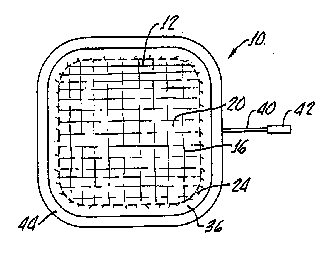
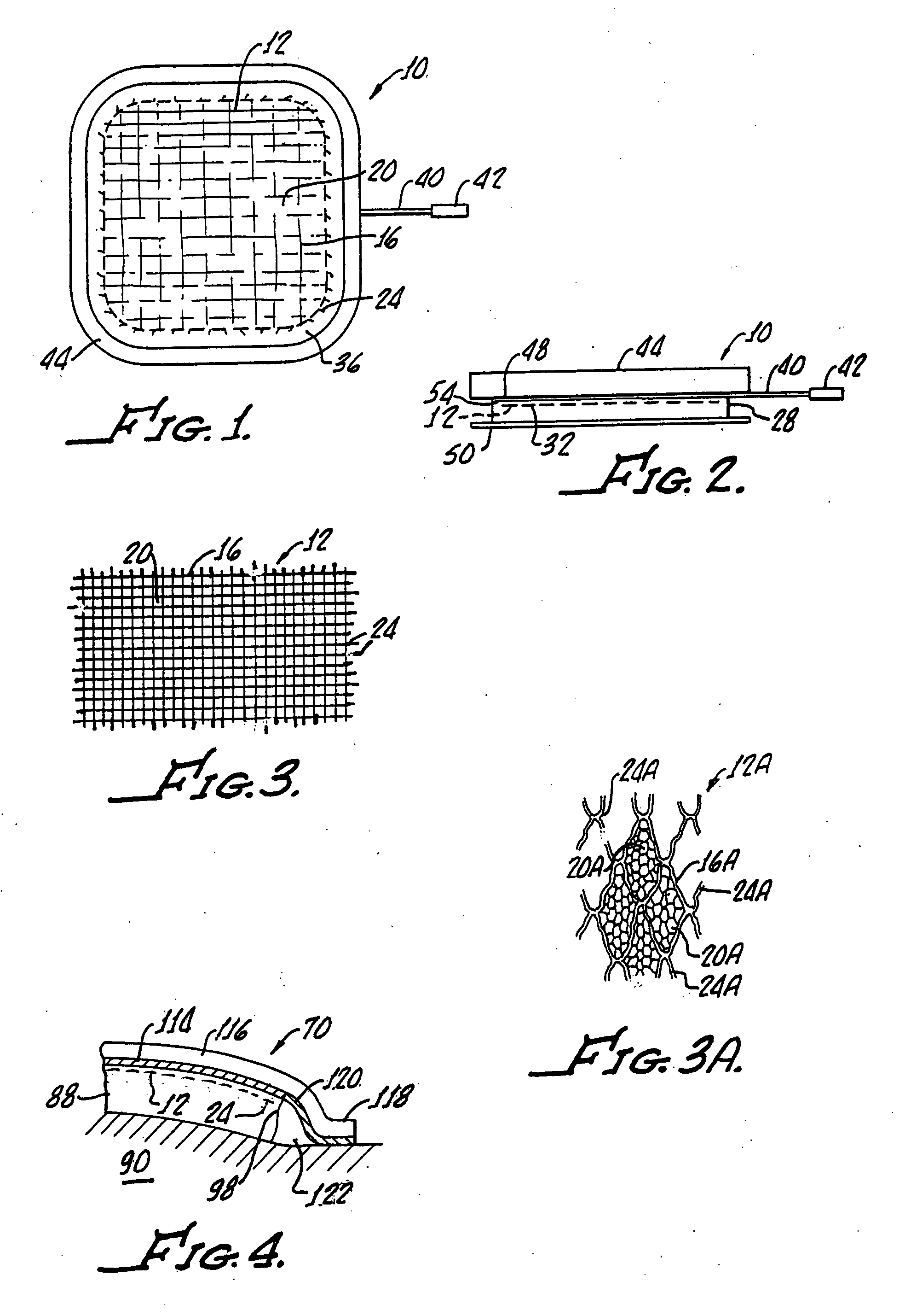
[0038]With reference to FIGS. 1 and 2, there is shown a flexible transcutaneous electrical nerve and / or muscle stimulation electrode 10 in accordance with the present invention. Conductive fabric 12, 12A best seen in FIGS. 3 and 3A includes fibers 16, 16A with interstitial areas 20, 20A therebetween. Any suitable conductive fabric 12, 12A may be utilized. As shown, the fabric 12, 12A may have loose ends, or frays, 24, 24A providing a potential for “hot spots” as hereinabove described.

[0039]A flexible conductive adhesive 28 of any suitable composition is disposed within the interstitial areas 20 and on one side 32 of the fabric 12, 12A as best seen in FIG. 2. The conductive adhesive 28 provides adherence of the electrode 10 to the skin of the patient (not shown) and provides an electrical conducting contact therebetween. As shown, the adhesive 28 has dimensions greater than corresponding dimensions of the conductive fabric 12, 12A in order to provide a border, or barrier portion, 36 ...


PUM


Abstract

A flexible transcutaneous electrical nerve and/or stimulation electrode includes a conductive fabric and a flexible conductive adhesive with a barrier portion surrounding a perimeter of the fabric for preventing extending and/or extendable frays of the fabric from extending exterior to the adhesive. An electrical lead wire interconnects the conductive fabric with an electrical stimulation device and a non-conductive sheet is disposed on another side of the conductive fabric for preventing undesirable electrical contact with the conductive fabric and providing a border seal.

Description

[0001]The present invention generally relates to electrodes and, more particularly, to electrodes suitable for transcutaneous nerve and / or muscle stimulation.[0002]Continued development of electrical medical devices has produced a need for a variety of electrodes.[0003]Although many of these electrodes have, as a design objective, good electrical signal transmission between a patient's skin surface and electrical leads interconnected with a device, each has specific requirements dependent upon the type of apparatus for which it is to be used.[0004]As an example, electrocardiograph (EKG) and electroencephalograph (EEG) machines are primarily monitoring type devices which require small contact surfaces, or area, with the patient's skin.[0005]On the other hand, transcutaneous electric nerve stimulation (TENS), and muscle stimulation devices require relatively large skin surface contact to effect such nerve and muscle stimulation.[0006]Transcutaneous electrical nerve stimulation is usef...

Claims


Application Information

Patent Timeline
IPC IPC(8): A61N1/04
CPCA61N1/0452A61N1/0492A61N1/0472A61N1/0456A61N1/04
Inventor AXELGAARD, JENS
Owner AXELGAARD MANUFACTURING COMPANY INC
Why Eureka
Try Eureka