Method and apparatus for delivering treatment to a joint

a treatment method and joint technology, applied in the field of apparatus and methods for treating disorders or trauma to joints, can solve the problems of only reducing inflammation, body to elicit an immune response, and deterioration of surrounding tissues, and achieve the effect of increasing patient complian

Inactive Publication Date: 2009-03-05
WARSAW ORTHOPEDIC INC
View PDF28 Cites 9 Cited by
  • Summary
  • Abstract
  • Description
  • Claims
  • Application Information

AI Technical Summary

Benefits of technology

[0022]Another object of the present invention is to provide for sustained-delivery of a biological agent from an implanted drug delivery device within a synovial joint to treat a trauma or disorder within such joint such that the use of the device obviates the need for regular dosing by the patient, thus increasing patient compliance with a prescribed therapeutic regimen, or in particular compliance with a prophylactic regimen prescribed prior to the onset of symptoms.

Problems solved by technology

In each of these disorders and traumas the joint is mechanically compromised either acutely or chronically causing the body to elicit an immune response.
Left unchecked, this can lead to degradation of surrounding tissues and associated chronic pain.
However, these types of treatment methods only reduce inflammation for a limited time span.
Nonetheless, both methods of the above two publications require compromising the integrity of the actual bone within the joint.
The long term effects of this method could lead to a weakening of the bone structure causing a fracture, infection, etc. within the synovial joint.
This, as stated above, weakens the integrity of the bone and, ultimately, the joint.
Moreover, suturing the depot to a ligament requires temporary damage to the ligament which can also disrupt the integrity of the joint and cause further damage and inflammation.

Method used


Image

  • Method and apparatus for delivering treatment to a joint
  • Method and apparatus for delivering treatment to a joint
  • Method and apparatus for delivering treatment to a joint

Examples


first embodiment

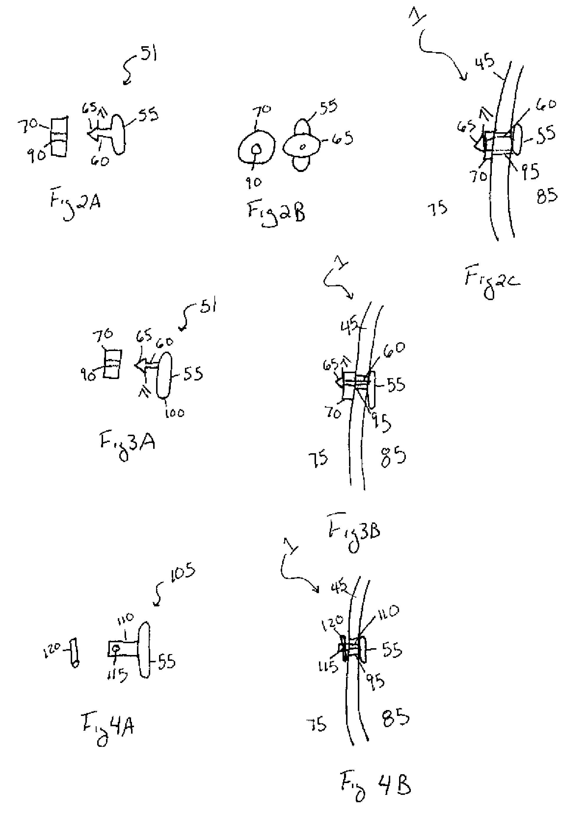
[0051]The above first embodiment of present invention is not limited to the recited structure of the depot 55, tether 60, and cap 70. More specifically, as illustrated in FIGS. 7A and 7B, the distal end 65 of the tether 60 may be adapted to receive the cap 70. For example, the tether 60 may contain a slot 66 with at least one groove 68 therein wherein the slot 66 functions as a female end of the tether 60. The cap contains at least one ridge 67 extending from one side of the cap wherein the ridges 67 function as a male end of the cap 70. To this end, the slot 66 is adapted to receive the ridge(s) 67 such that the ridge(s) 67 of the cap 70 are press fit or snapped into the slot 66 of the distal end 65 of the tether 60. Alternatively, the ridge 67 and groove 68 may be adapted such that the cap threadingly engages the tether. In either case, the groove(s) 68 of the slot 66 match up with the ridge(s) 67 of the cap such that the cap 70 is frictionally secured within the tether. As illust...

second embodiment

[0093]The second embodiment is advantageous in that the distance between the tether 60 and the opposing end 100 of the depot 55 is greater. Accordingly, the depot 55 may be implanted into the synovial joint 1 with greater ease. Moreover, a small incision 95 in the membrane 45 is all that is required to implant the depot 55 within the synovial joint 1. This, in turn, reduces the risk of any adverse consequences stemming from implantation of the device such as, but not limited to, leakage of the synovial fluid, infection, or any further complications.

[0094]Referring to FIG. 4A and FIG. 4B a third embodiment of the present invention is illustrated. In the third embodiment, the depot 55 may be a rod, as illustrated in FIG. 4A, a disc, a cylinder, or any other shape understood in the art to act as a sustained-release drug device or depot. The depot 55 may take the form of any solid, biodegradable, natural or synthetic polymer or combinations thereof, as discussed above, and may contain a...

third embodiment

[0097]An advantage of this third embodiment is that the depot may be implanted within the synovial joint with greater ease. Accordingly, the structural integrity of the membrane 45 is maintained and there is less risk of infection and / or synovial fluid or biological agent leaking from the synovial joint.

[0098]Referring to FIGS. 5A, 5B, and 5C a fourth embodiment of the present invention is illustrated. In the fourth embodiment, the depot 55 may be a rod, as illustrated in FIG. 5A, a disc, a cylinder, or any other shape understood in the art to act as a sustained-release drug device or depot. The depot 55 may be composed of any solid, biodegradable, natural or synthetic polymer or combinations thereof, as discussed above, and may contain at least one biological agent, as discussed above. The tether 130 of the fourth embodiment may be, but is not limited to, at least one suture extending from the depot 55. The length of the tether 110 may be of any length necessary for implantation in...


PUM


Abstract

The present invention relates to an apparatus and method for treating inflammation and/or infection within a synovial joint. The invention is comprised of a depot, tether and cap. The depot is comprised of a biodegradable polymer which is impregnated with a biological agent targeted to treat the inflammation and/or infection. The depot is inserted into the synovial joint through an incision or hole in the synovial membrane. A tether that extends from the depot is then thread back through the incision or hole and coupled to a cap such that the depot is coupled to the synovial membrane on an interior side of the synovial joint capsule and the cap is secured to the membrane on an exterior side of the synovial joint capsule. Once secured, the depot degrades and gradually releases the biological agent over a sustained time period. The biological agent then treats the targeted inflammation and/or infection.

Description

FIELD OF THE INVENTION[0001]The present invention relates to an apparatus and method for treating a disorder or trauma to a joint of a subject's body. More specifically, the present invention relates to surgically implanting a depot within the joint such that the depot delivers a biological agent to the joint. In one embodiment, the depot contains a biological agent that is implanted on the interior surface of the joint capsule of a synovial joint, such as, but not limited, to a knee joint. The depot may be biodegradable such that, as the depot degrades within the body, the biological agent is gradually released to treat the targeted disorder or trauma.BACKGROUND OF THE INVENTION[0002]Synovial joints, such as the knee, are joints of the body wherein two adjacent bones are coupled and encapsulated within a synovial membrane or capsule. Referring to FIG. 1A and FIG. 1B, one embodiment of a synovial joint is illustrated as, but not limited to, a human knee joint 1. The joint 1 is compr...

Claims


Application Information

Patent Timeline
Patent Type & Authority Applications(United States)
IPC IPC(8): A61F2/30A61F13/20
CPCA61B17/00234A61B17/0057A61B17/0401A61B17/0487A61B17/0643A61K9/0024A61B2017/00659A61B2017/00663A61B2017/00668A61B2017/0496A61B2017/00004
Inventor MCKAY, WILLIAM F.
Owner WARSAW ORTHOPEDIC INC
Why Eureka
Try Eureka