Methods for detecting oil deterioration and oil level
Inactive Publication Date: 2009-03-05
SUN YIZHONG
View PDF19 Cites 27 Cited by
Summary
Abstract
Description
Claims
Application Information
AI Technical Summary
This helps you quickly interpret patents by identifying the three key elements:
Problems solved by technology
Method used
Benefits of technology
Benefits of technology
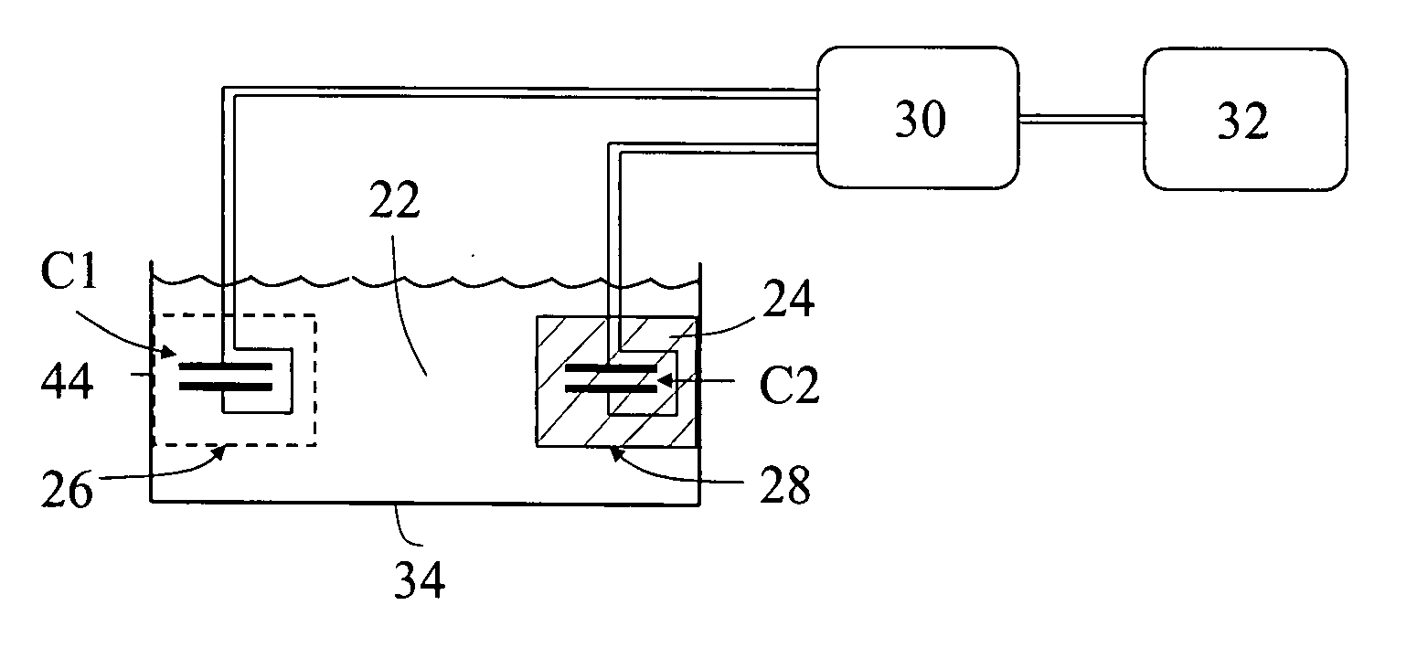
[0046]In a situation during the oil deterioration when the amount of the oil is not significantly reduced so that the capacitor is still fully immersed in the oil, the electrical property of the capacitor is influenced by increase of the dielectric constant of the oil due to progress of the oil deterioration, or by significant increase of the dielectric constant due to presence of water in the oil. In another situation when the amount of the oil is significantly reduced to the predetermined threshold amount, it causes a lower top oil level, which is insufficient for the sensing capacitor being fully immersed in the oil, so that the capacitor is partially filled with the air. According to this condition, the electrical property of the capacitor is predominantly influenced by the dielectric constant of the air which is substantially smaller than the oil dielectric constant.
[0047]In accordance with a first preferred embodiment of the present invention methods, a reference capacitor is also used in addition to the sensing capacitor. The reference capacitor is immersed in a reference oil including a dry new oil or a dry spent oil or a dry partially spent oil having the same thermal properties as those of the oil in use. The reference oil and the oil in use are placed in the same temperature environment. In addition, the reference capacitor has defined structural parameters so that the sensing and reference capacitors exhibit the same change of the electrical property according to the oil temperature change when they are immersed into the same oil. In the first preferred embodiment, the electrical properties of the sensing and reference capacitors are combined, thereby eliminating fluctuations of the measured electrical property of the sensing capacitor, where the fluctuations are induced by variations of the oil temperature. Therefore, the preferred embodiment of the present invention enables to obtain a measured temperature compensated electrical property of the sensing capacitor. In this manner, a predicted temperature compensated electrical property profile for the oil also can be simulated, which reflects an entire deterioration for the oil when it is dry.
[0051]Obtaining the above illustrated abnormal oil conditions, the user of the machine can taking appropriate actions to protect the machine from damage.
[0067]It is a further additional object of the present invention to apply at least two measurement sensors which are positioned at different levels of the oil system, wherein the first of the at least two sensors is positioned whose sensing capacitor is aligned with a level that is adjacent and below a top level of the oil which is newly replaced, and second of the at least two sensor is positioned whose sensing capacitor is aligned with the top level of a threshold amount of the oil, so that a detailed information can be obtained for reduction of the top level of the oil in the oil system.
Problems solved by technology
In another situation when the amount of the oil is significantly reduced to the predetermined threshold amount, it causes a lower top oil level, which is insufficient for the sensing capacitor being fully immersed in the oil, so that the capacitor is partially filled with the air.
Method used
Image
Click on the blue label to locate the original text in one second.
Reading with bidirectional positioning of images and text.
Examples
first embodiment
[0138]Therefore, the present invention continually comprises the following step:
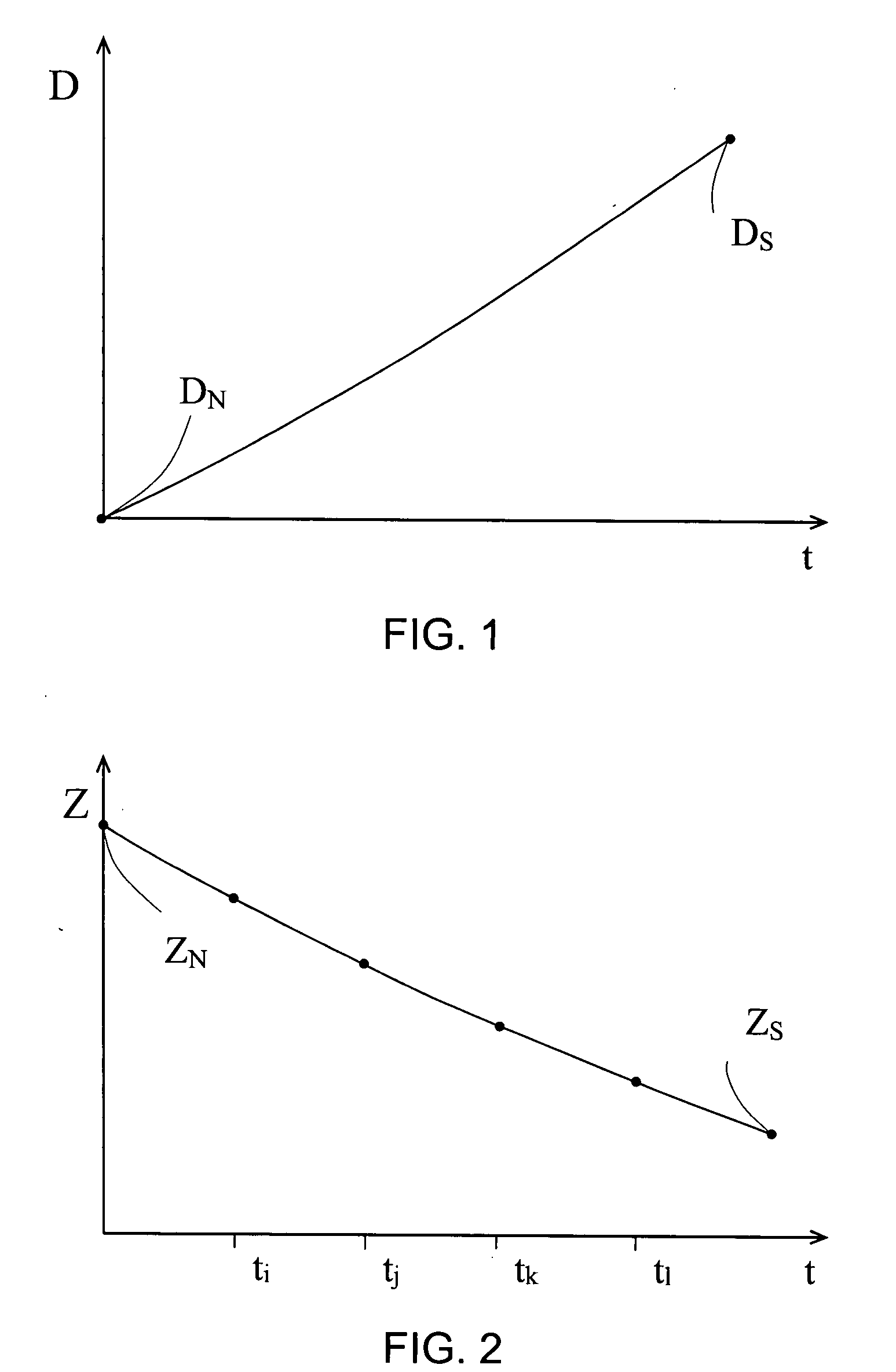
[0139](h) following the steps (a) to (g) establishing a predicted temperature compensated electrical property profile for the oil, which reflects the normal oil deterioration, the predicted profile includes an electrical property (EPT,N), which is equal to a measured property EPT(M) of the oil if it is unused and dry, and another electrical property (EPT,S), which is equal to the measured property EPT(M) of the oil if it is spent and dry.
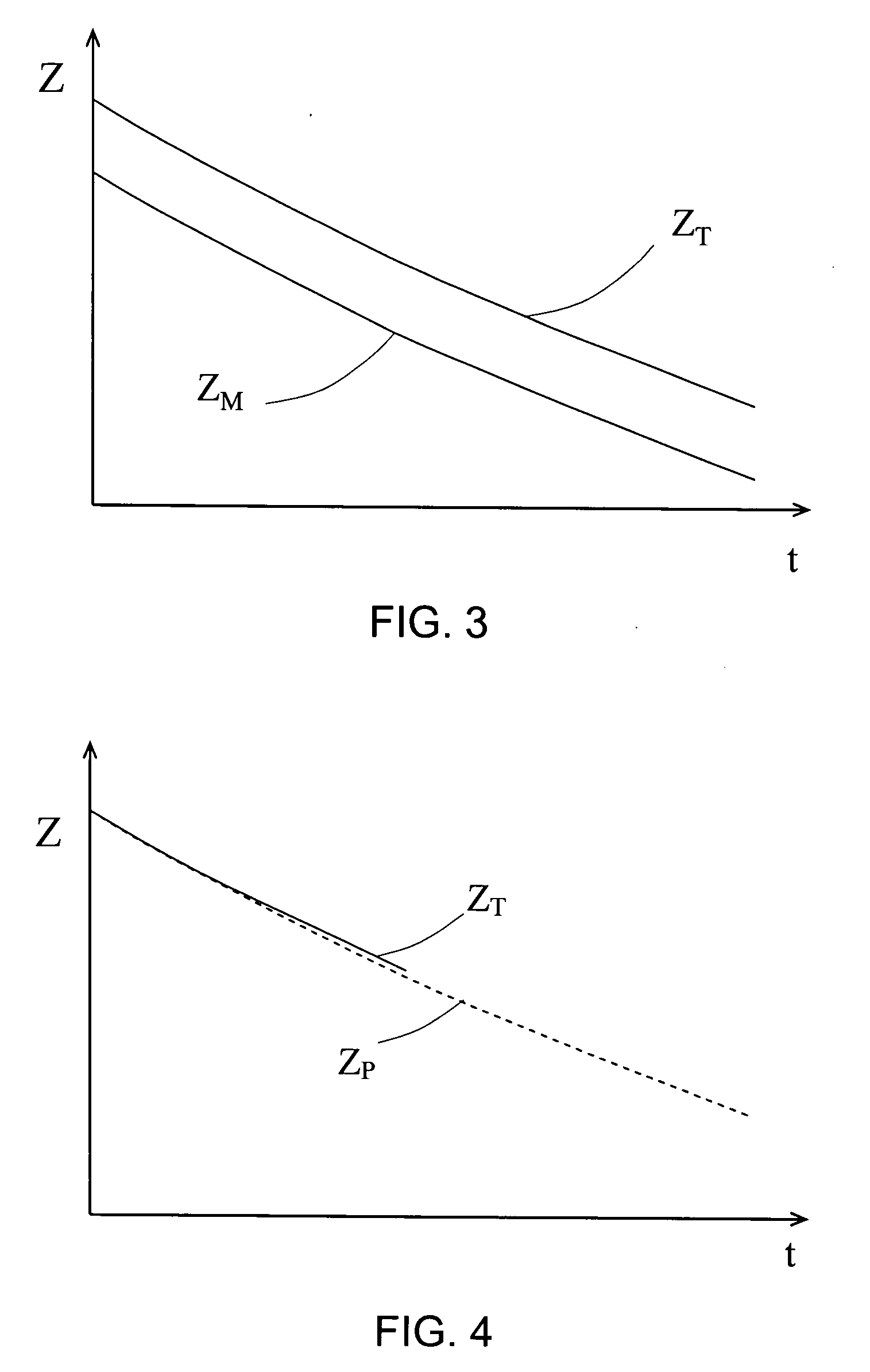
[0140]Now the normal oil deterioration, which has been briefly disclosed in FIG. 4, will be illustrated in detail in FIGS. 13 and 14. FIGS. 13 and 14 illustrate the same situation of the normal oil deterioration, where the measured electrical property profile EPT(M) is consistent with the predicted one EPT(P). It will be appreciated that, for a comparison with an abnormal oil deterioration in later discussion, a partial of the measured property profile is presented in th...
second embodiment
[0195]In addition, following the above disclosed procedures which is used for obtaining the measured temperature compensated electrical property of the oil in step “d”, the present invention further comprises a step (e):
[0196](e) establishing a predicted temperature compensated electrical property profile for the oil, which reflects the normal oil deterioration, the predicted profile includes an electrical property (EPT,N), which is equal to a measured property EPT(M) of the oil if it is unused and dry, and another electrical property (EPT,S), which is equal to the measured property EPT(M) of the oil if it is spent and dry.
[0197]Once after establishing the predicted property profile EPT(P), the second preferred embodiment of the present invention can apply all the same strategies thus the same claims of the first preferred embodiment, including a comparison of the measured remaining usage in the respective two forms (RΔU) and (ΔU) with the predicted remaining usage to conclude if th...
PUM
Abstract
Methods for detecting oil conditions including a top oil level in an oil system which is reduced to a top level of a threshold amount of the oil, a normal oil deterioration which occurs in the absence of water having a confirmed remaining oil usage, and an abnormal oil deterioration which occurs in the presence of water. The methods comprise a first preferred embodiment which applies a reference and sensing capacitors to obtain a measured temperature compensated electrical property of an oil in use. From which a quantitatively measured remaining usage is obtained so as to a predicted one for the oil. Therefore, the respective top oil level, or the normal or the abnormal oil deterioration can be concluded according to the measured remaining usage which is respectively larger than, or similar to, or less than the predicted one for the oil. A second preferred embodiment only includes the sensing capacitor for obtaining the measured property of the oil. Variations to the embodiments lead to employment of at least two sensing capacitors to monitor an uneven distribution of the oil deterioration or a full range of the oil level of the entire oil system.
Description
BACKGROUND OF INVENTION[0001]1. Field of the Invention[0002]The present invention is generally related to oil which is used in machinery such as internal combustion engines and electrical transformers, and more particularly related to methods for the on-line detection of the oil level, and the oil deterioration which occurs in the presence or absence of water.[0003]2. Description of the Prior Art[0004]Devices and methods for detecting oil deterioration and oil level are well known. The following 20 patents and published patent applications are the closest prior art references which are related to the present invention.[0005]1. U.S. Pat. No. 4,517,547 issued to Gary et al. on May 14, 1985 for “Water-In-Fuel Sensor Circuit And Method” (hereafter the “Gary patent”);[0006]2. U.S. Pat. No. 4,646,070 issued to Yasuhara et al. on Feb. 24, 1987 for “Oil Deterioration Detector Method And Apparatus” (hereafter the “Yasuhara patent”);[0007]3. U.S. Pat. No. 4,764,258 issued to Kauffman on Aug. ...
Claims
Application Information
Patent Timeline
Application Date:The date an application was filed.
Publication Date:The date a patent or application was officially published.
First Publication Date:The earliest publication date of a patent with the same application number.
Issue Date:Publication date of the patent grant document.
PCT Entry Date:The Entry date of PCT National Phase.
Estimated Expiry Date:The statutory expiry date of a patent right according to the Patent Law, and it is the longest term of protection that the patent right can achieve without the termination of the patent right due to other reasons(Term extension factor has been taken into account ).
Invalid Date:Actual expiry date is based on effective date or publication date of legal transaction data of invalid patent.

