Typically Spherical Applicator Tip For Application Of Cosmetic Products

a cosmetic product and applicator tip technology, applied in the field of cosmetic product application agents, can solve problems such as accumulation of too many cosmetic products, and achieve the effect of great make-up sharpness

Active Publication Date: 2009-03-12
ALBEA SERVICES SAS
View PDF4 Cites 29 Cited by
  • Summary
  • Abstract
  • Description
  • Claims
  • Application Information

AI Technical Summary

Benefits of technology

[0024]The applicator tips according to the invention make it possible to solve the problems raised. Indeed, they have a geometrical configuration which is distinct, in particular through its shape and size, from those of the molded brushes and applicators of the state of the art, which makes it possible in particular to produce a great make-up sharpness even in the lesser accessible parts of the face.
[0025]According to a particularly preferred embodiment of the invention, the core is a core which substantially defines a truncated sphere with radius R, the truncation of the sphere corresponding to the junction between the core and the handle member. This rounded shape of the core advantageously makes it possible to obtain an applicator tip having a rounded surface of envelope without hollows that are too deep between the projections. As a matter of fact, hollows which are too deep could cause an accumulation of too much cosmetic product due to the fact that it is difficult to combine an applicator having a rounded surface of envelope with an efficient wiper. Thus, in view of the shape of this core, it is possible to obtain a rounded surface of envelope with projections of substantially identical sizes so that the properties of the projections, for example softness, are homogenous, which allows for a homogenous application of the cosmetic product.

Problems solved by technology

As a matter of fact, hollows which are too deep could cause an accumulation of too much cosmetic product due to the fact that it is difficult to combine an applicator having a rounded surface of envelope with an efficient wiper.

Method used


Image

  • Typically Spherical Applicator Tip For Application Of Cosmetic Products
  • Typically Spherical Applicator Tip For Application Of Cosmetic Products
  • Typically Spherical Applicator Tip For Application Of Cosmetic Products

Examples


examples

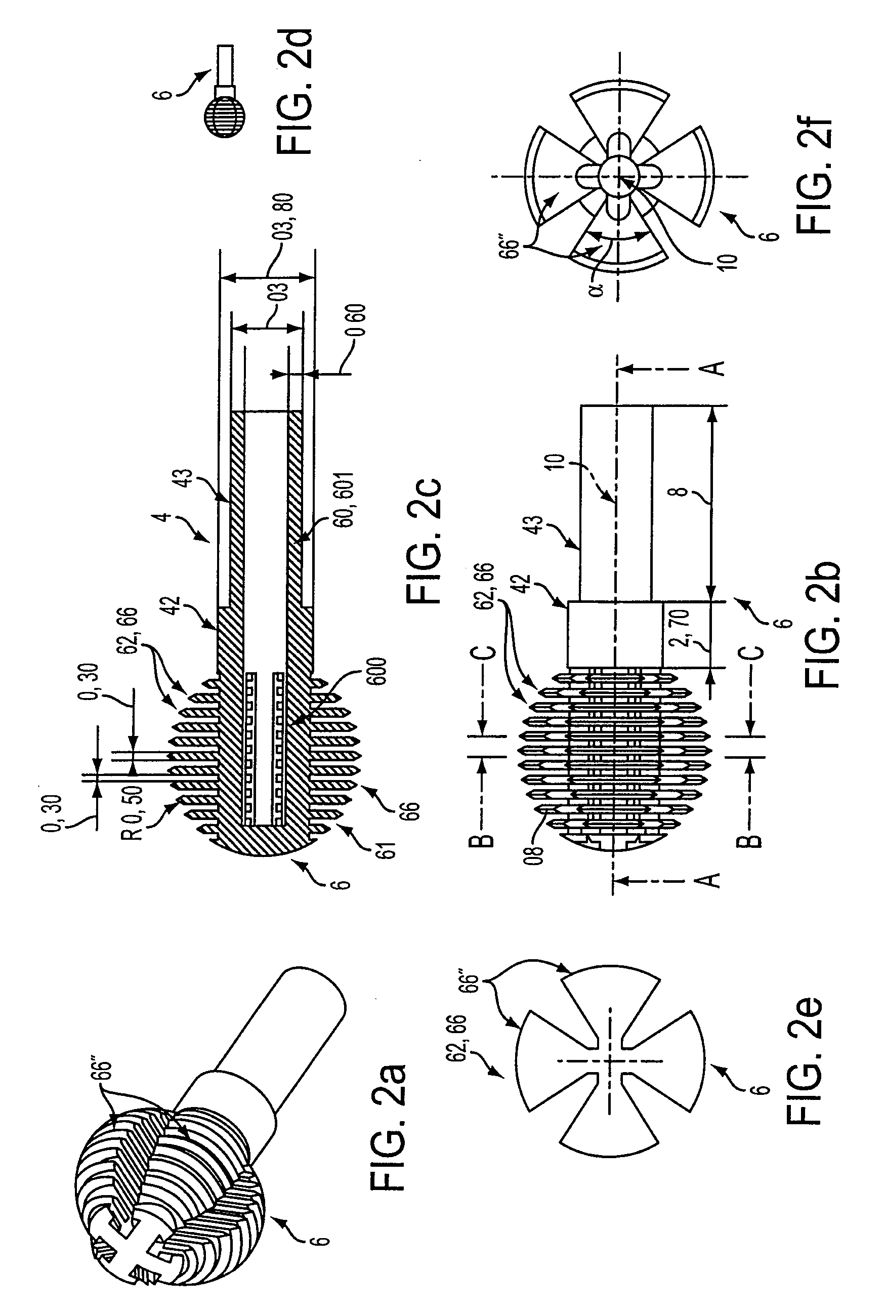
[0096]I) Tips 1,1″ constituting single-piece molded members 6 of plastic material, according to FIGS. 1a to 5c, were manufactured by molding.

[0097]Tests were made with PE and with an elastomer, however any plastic material that can be molded for allowing to simultaneously constitute an axial handle member 4 which is relatively rigid to make sure that the tip 1 is fixedly mounted on rod 20 of applicator 2 and an application means 3,3″ comprising a plurality of relatively flexible projections 31, may be used.

[0098]To manufacture these tips by molding, the process described in FIGS. 6a to 7j was used, in particular whenever this was required by the stripping stresses.

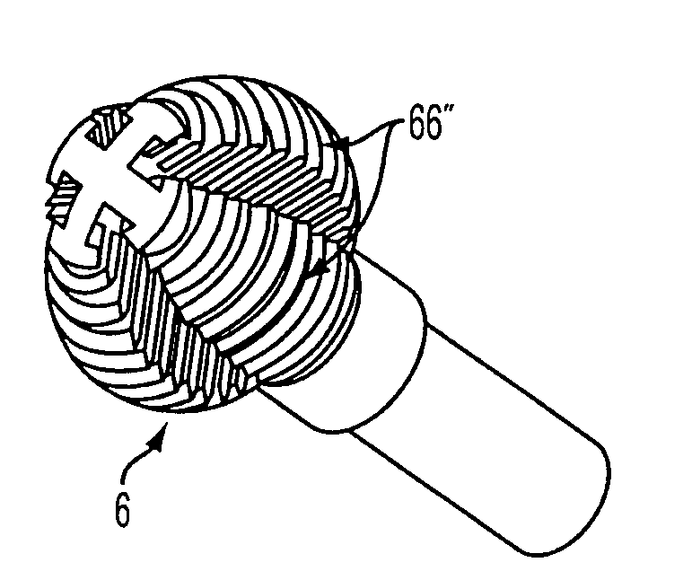
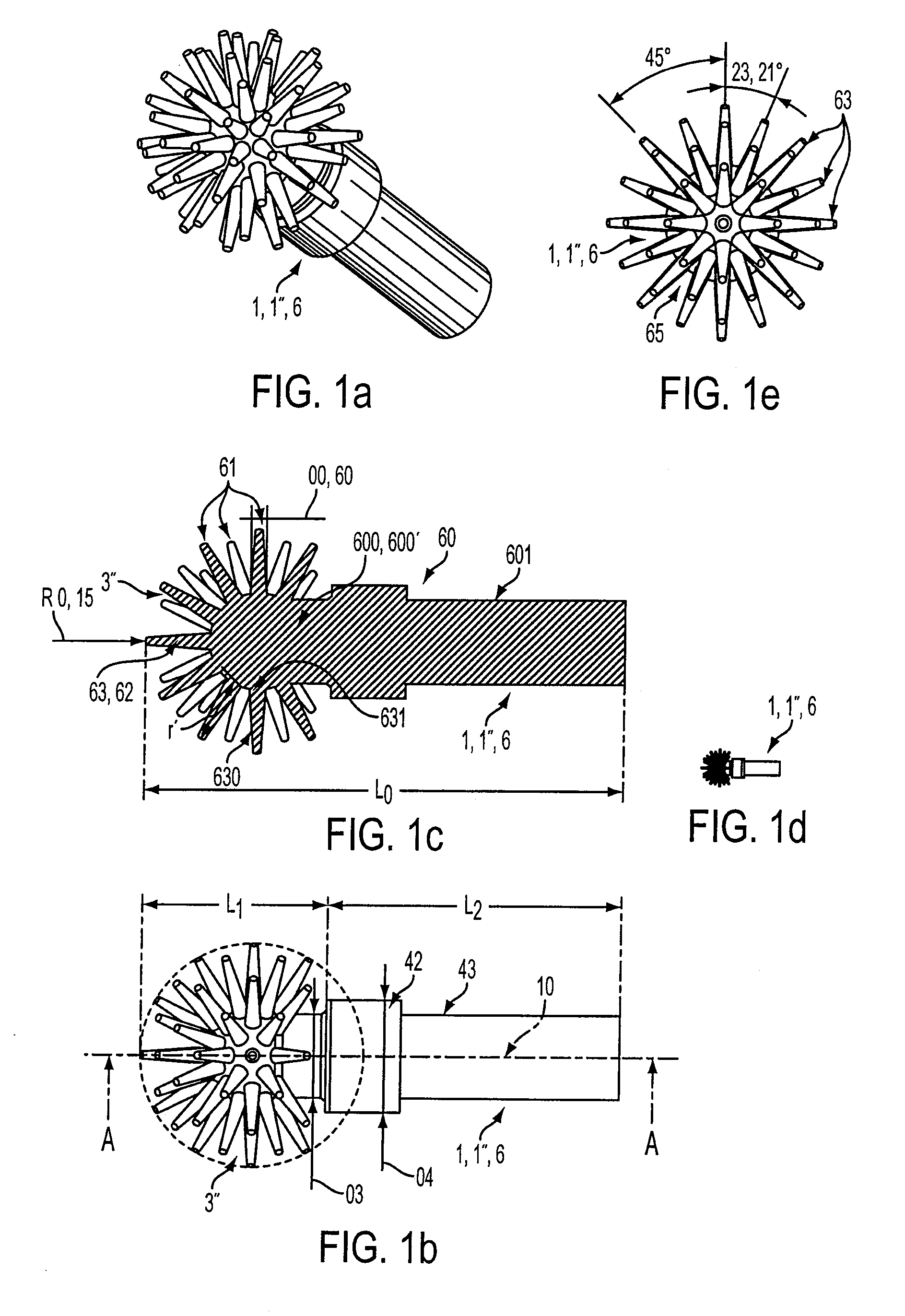
[0099]I-1) The tip 1,1″ according to FIGS. 1a to 1e was produced.

[0100]This applicator tip has an axial length L0 of 16 mm.

[0101]Its application means 3,3″ comprises a plurality of hexagonally arranged 65 projections 61. The core 600,600′ constitutes a truncated sphere 3.5 mm in diameter, the plurality of projections 61 ly...


PUM

PropertyMeasurementUnit
length L2aaaaaaaaaa
length L2aaaaaaaaaa
length L2aaaaaaaaaa

Abstract

The applicator tip comprises:
    • a) an application means comprising a rigid core and a plurality of flexible projections,
    • b) an axial handle member having an axial direction and comprising an upper end adapted to be fixedly connected to a rod, and operatively associated with the rigid core through its lower end, and characterized in that:
    • 1) the applicator tip has, along the axial direction, a length L0 ranging from 10 mm to 30 mm, application means having a length L1 which ranges from 6 mm to 15 mm, wherein Lo=L1+L2,
    • 2) the application means having a transverse width T, taken in a transverse plane, which is variable as a function of the axial distance L which varies from 0 to L1, the function T=f(L) having a maximum value of T1 for the transverse width when L is between 0.3. L1 and 0.7. L1.

Description

BACKGROUND OF THE INVENTION[0001](a) Field of the invention[0002]The invention concerns the field of applicators for cosmetic products, typically make-up products for the eyes and lips.[0003](b) Description of Prior Art[0004]A very large number of applicators of all kinds, in particular in the field of skin and eye care, and particularly of the eyes, with mascara applicators, are already known.[0005]There applicators, which are adapted to operate jointly with a container defining a reservoir for mascara, typically comprise:[0006]a) a cap adapted to seal the container and to be used as prehension means for the applicator,[0007]b) and axial rod,[0008]c) and a brush,[0009]the rod being unitary with the cap at one of its ends, and with the brush at the other end thereof, the brush comprising a metallic twist on which a plurality of bristles are fixedly mounted.[0010]With respect to the brush, a very large number of embodiments of brushes are already known.[0011]Thus, the brushes describ...

Claims


Application Information

Patent Timeline
Patent Type & Authority Applications(United States)
IPC IPC(8): A45D40/28A45D40/26B29D31/00B29D99/00
CPCA45D40/262A46B3/005A46B9/021A46B2200/106A46B9/028A46B2200/1053A46B9/025
Inventor BERHAULT, ALAIN
Owner ALBEA SERVICES SAS
Why Eureka
Try Eureka