Poly-phase frequency synthesis oscillator

a technology of poly-phase frequency synthesis and oscillator, which is applied in the direction of oscillator generator, pulse technique, frequency change manipulation, etc., can solve the problems that the conventional phase lock loop circuit can consume a large amount of area on the integrated circuit and may also utilize significant amounts of power

Active Publication Date: 2009-03-12
MONTEREY RES LLC
View PDF99 Cites 34 Cited by
  • Summary
  • Abstract
  • Description
  • Claims
  • Application Information

AI Technical Summary

Problems solved by technology

While a conventional phase locked loop 20 provides a wide range of flexibility in design for use in circuit applications that have different frequency requirements, a conventional phase lock loop circuit can consume a large amount of area on an integrated circuit and may also utilize significant amounts of power.

Method used


Image

  • Poly-phase frequency synthesis oscillator
  • Poly-phase frequency synthesis oscillator
  • Poly-phase frequency synthesis oscillator

Examples


Embodiment Construction

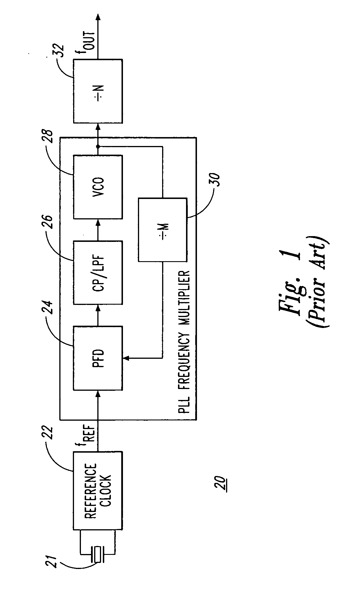
[0025]Disclosed herein are various embodiments of a circuit and method for multiplying the frequency of a reference clock to generate an output signal that has a frequency that is a multiple of the reference clock frequency. Embodiments of the present invention may be used, for instance, to generate an output clock signal that has a frequency that is, for example, a small integer value multiple of the frequency of the reference signal. Embodiments of the present invention may be implemented so as to provide a low power and area efficient alternative to a conventional phase locked loop solution.

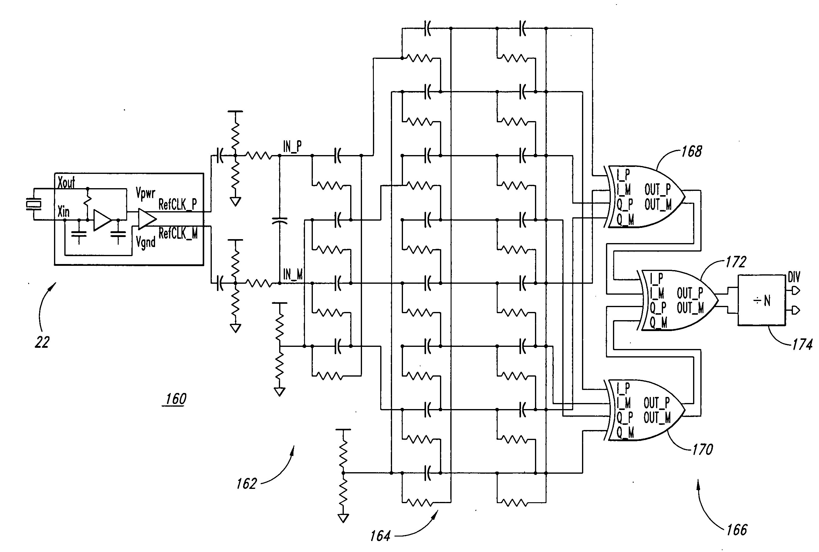
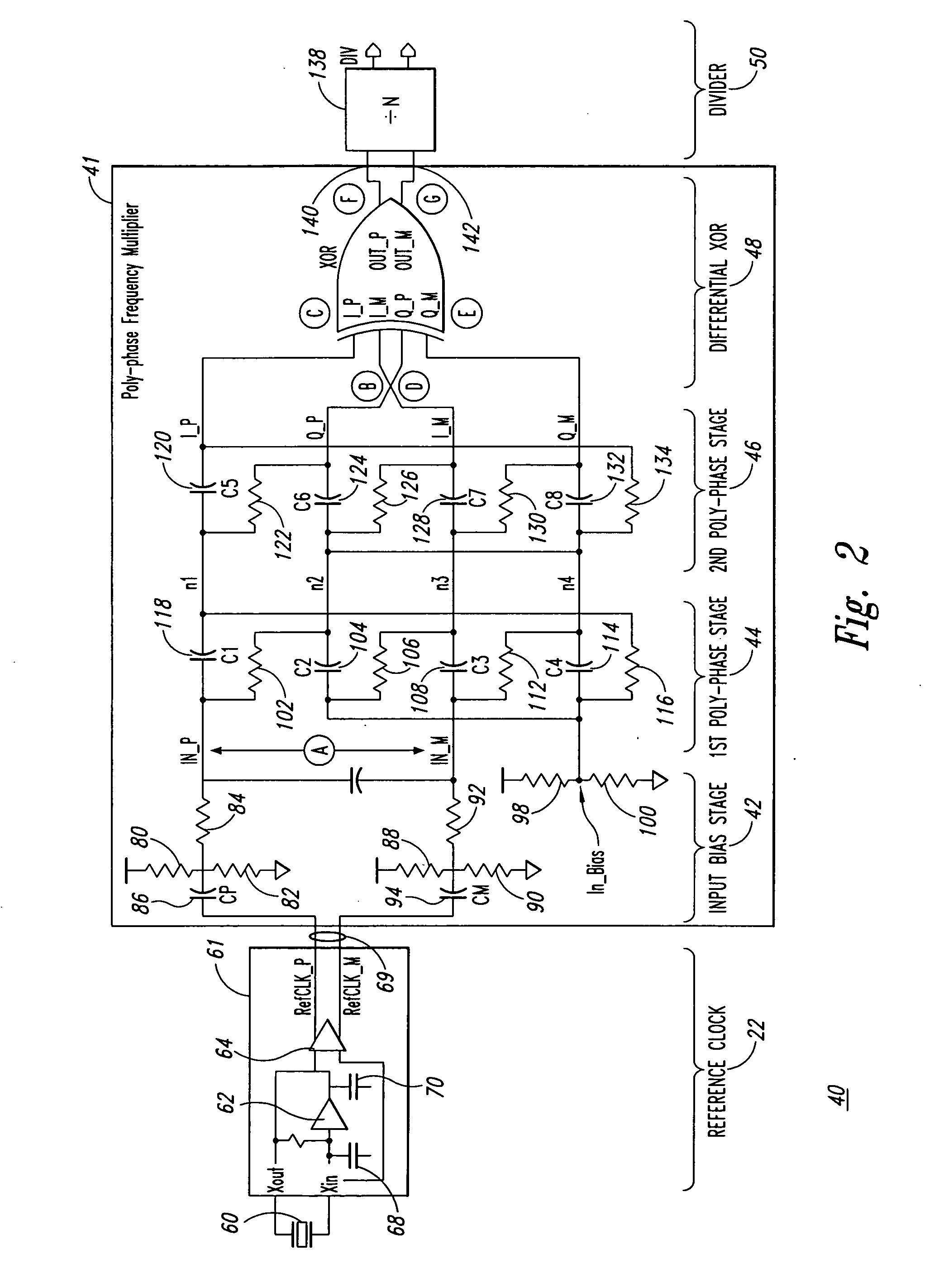
[0026]In one example of the present invention, a circuit may comprise a crystal oscillator or other conventional clock generation circuit that produces a differential sinusoidal reference clock; a multi-stage poly-phase filter for generating multiple phases (or delayed versions) of the reference signal; and logic, such as combinatorial logic gates such as a differential XOR gate, that combines...


PUM


Abstract

A frequency synthesis / multiplication circuit and method for multiplying the frequency of a reference signal. In one embodiment, multiple versions of the reference signal are generated having different phases relative to one another, and these multiple versions are combined to form an output signal having a frequency that is a multiple of the frequency of the reference signal.

Description

CROSS REFERENCE TO RELATED APPLICATION[0001]This application claims priority under 35 U.S.C. 119(e) to U.S. Provisional Patent Application No. 60 / 650,057 entitled “POLY-PHASE FREQUENCY SYNTHESIS OSCILLATOR” filed Feb. 4, 2005, the disclosure of which is hereby incorporated by reference in its entirety.FIELD OF THE INVENTION[0002]The present invention relates generally to electronic circuits, and more particularly to oscillator circuits or clock circuits.BACKGROUND OF THE INVENTION[0003]Phase lock loop (PLL) circuits are typically used to provide or generate a clock signal that is an integer fraction or integer multiple of a crystal oscillator reference frequency.[0004]FIG. 1 illustrates a conventional phase lock loop architecture. A reference clock 22 generates a reference clock signal having a reference frequency, and the reference clock signal may be coupled with a phase / frequency detector 24 which may be coupled with a low pass filter 26. The output of the low pass filter 26, whi...

Claims


Application Information

Patent Timeline
Patent Type & Authority Applications(United States)
IPC IPC(8): H03B19/00
CPCG06F7/68H03H7/21H03K5/1565H03K5/00006H03H2007/0192
Inventor BRENNAN, AARON
Owner MONTEREY RES LLC
Why Eureka
Try Eureka