
Method and apparatus for frequency synthesis

a frequency synthesis and frequency technology, applied in the field of frequency synthesis, can solve the problems of not being able to integrate all delay elements onto a single integrated circuit, many delay elements or quantization steps would be required, implementation problems,

Active Publication Date: 2006-03-30
MOTOROLA SOLUTIONS INC
View PDF11 Cites 32 Cited by
  • Summary
  • Abstract
  • Description
  • Claims
  • Application Information

AI Technical Summary

Benefits of technology

[0055] While the invention has been described in conjunction with specific embodiments thereof, additional advantages and modifications will readily occur to those skilled in the art. The invention, in its broader aspects, is therefore not limited to the specific details, representative apparatus, and illustrative examples shown and described. Various alterations, modifications and variations will be apparent to those skilled in the art in light of the foregoing description. Thus, it should be understood that the invention is not limited by the foregoing description, but embraces all such alterations, modifications and variations in accordance with the spirit and scope of the appended claims.

Problems solved by technology

Thus, to obtain the spurious requirements for certain applications, thousands of delay elements or quantization steps would be required.
However, this presents implementation problems.
For example, depending on the number of delay elements required, it may not be possible to integrate all of the delay elements onto a single integrated circuit.
Moreover, if an active delay cell approach were used, this would negatively impact overall current drain.
Nonetheless, if a passive delay cell (e.g. a transmission line) approach were used, the performance of the DPC would be highly susceptible to process variation (which could negatively impact monotonicity) due to mismatch or loading and result in a loss of performance.
In addition, the passive delay element approach is not portable to future IC technologies.

Method used


Image

  • Method and apparatus for frequency synthesis
  • Method and apparatus for frequency synthesis
  • Method and apparatus for frequency synthesis

Examples


Embodiment Construction

[0023] While this invention is susceptible of embodiments in many different forms, there are shown in the figures and will herein be described in detail specific embodiments, with the understanding that the present disclosure is to be considered as an example of the principles of the invention and not intended to limit the invention to the specific embodiments shown and described. Further, the terms and words used herein are not to be considered limiting, but rather merely descriptive. It will also be appreciated that for simplicity and clarity of illustration, elements shown in the figures have not necessarily been drawn to scale. For example, the dimensions of some of the elements are exaggerated relative to each other. Further, where considered appropriate, reference numerals have been repeated among the figures to indicate corresponding elements.

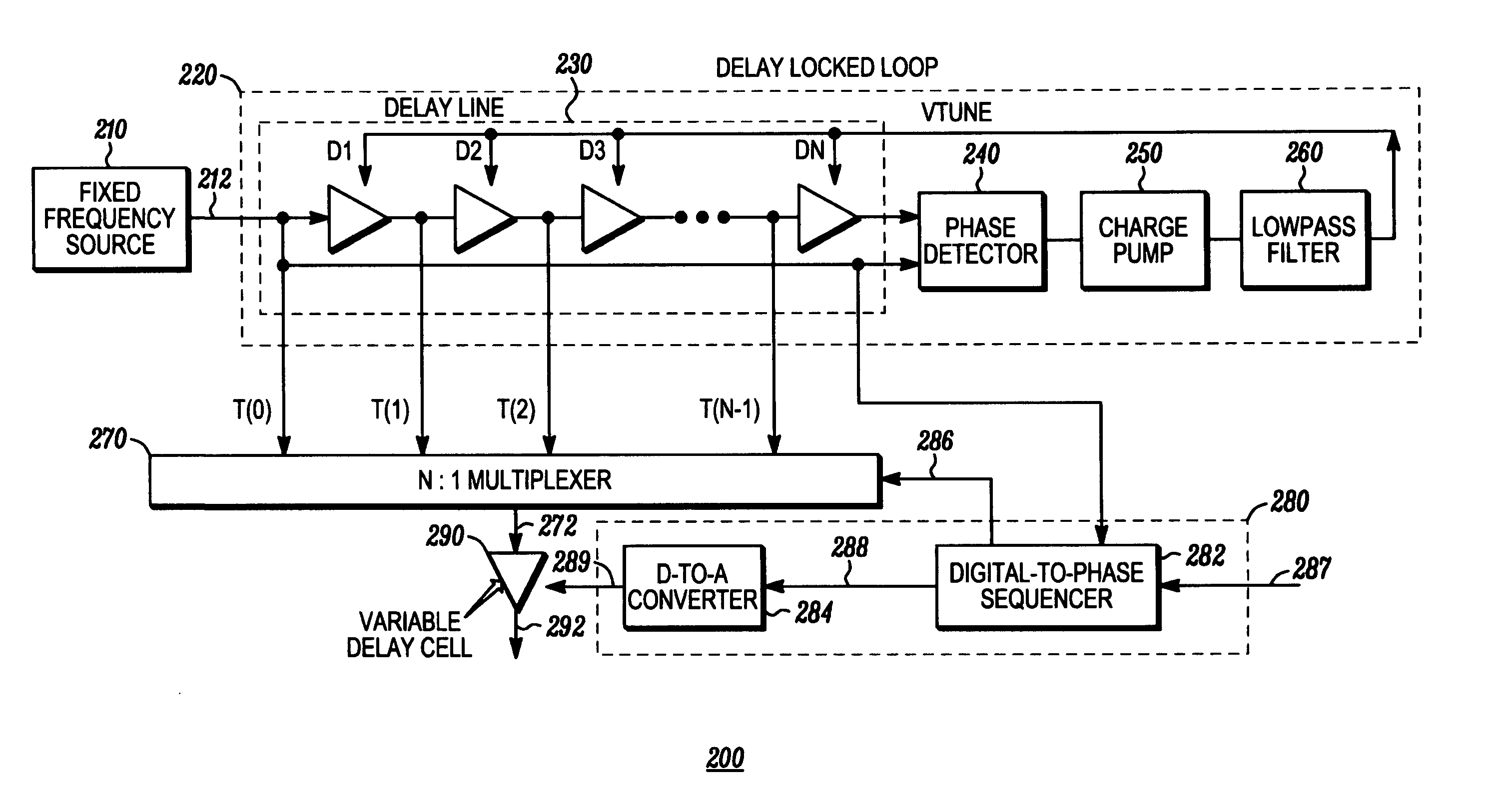
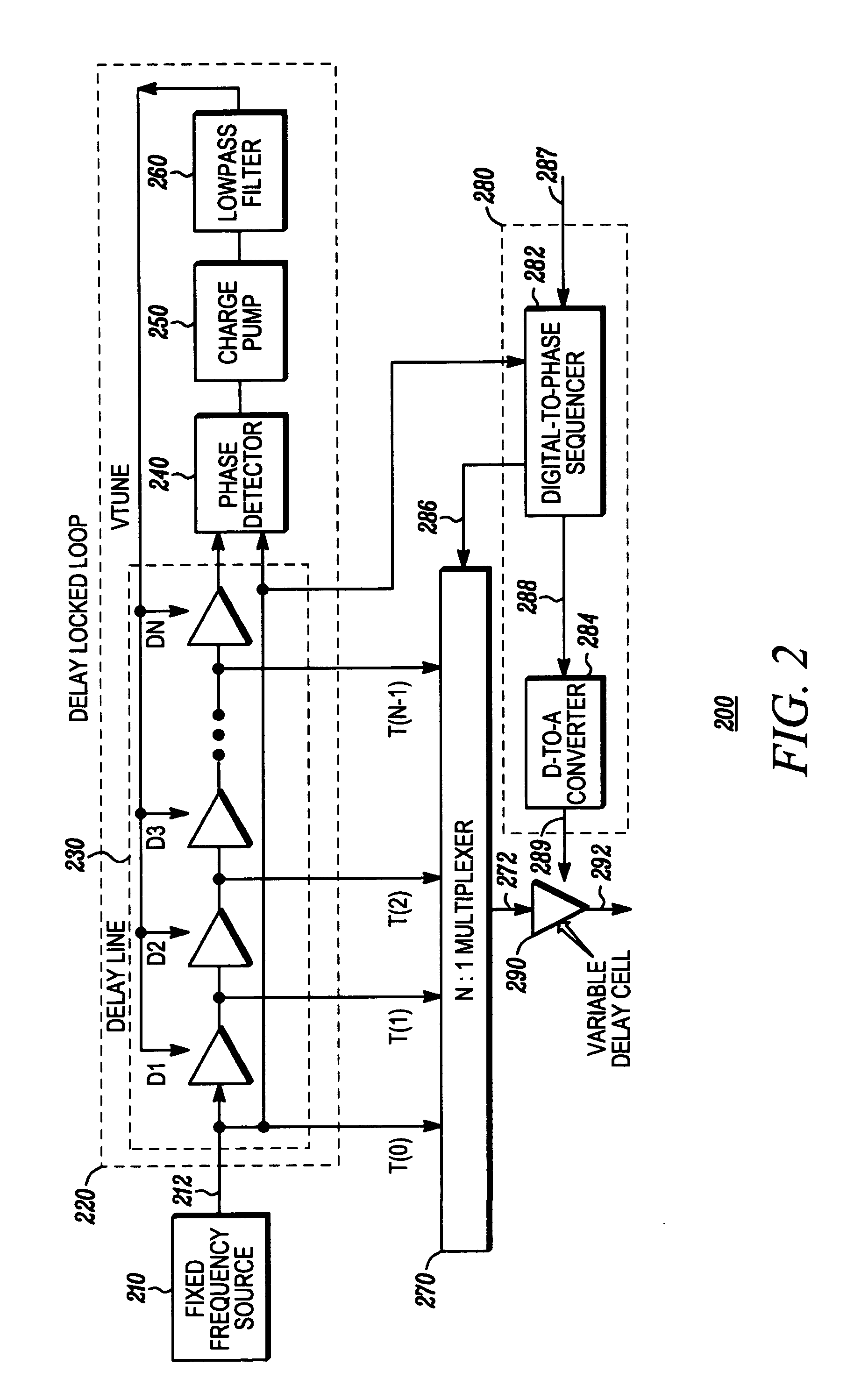
[0024]FIG. 2 illustrates a block diagram of a DPC 200 in accordance with an embodiment of the present invention for generating a synth...


PUM


Abstract

A DPC (200) that includes: a frequency source (20); a delay-locked loop (220) for receiving a clock signal and generating a plurality of phase-shifted clock signals; a control device (280) having a DPS (282) and a DAC (284) for receiving an input signal identifying a desired frequency for a synthesized signal; a selection circuit (270) for receiving the plurality of phase-shifted clock signals, selecting a sequence of the phase-shifted clock signals and outputting a coarse synthesized signal; a variable delay cell (290) having a first input coupled to the selection circuit to receive the coarse synthesized signal and a second input coupled to the control device for receiving a fine tune adjustment signal to modify the coarse synthesized signal to generate the synthesized signal (292) having substantially the desired frequency. The DPC further includes training apparatus for calibrating the DPC.

Description

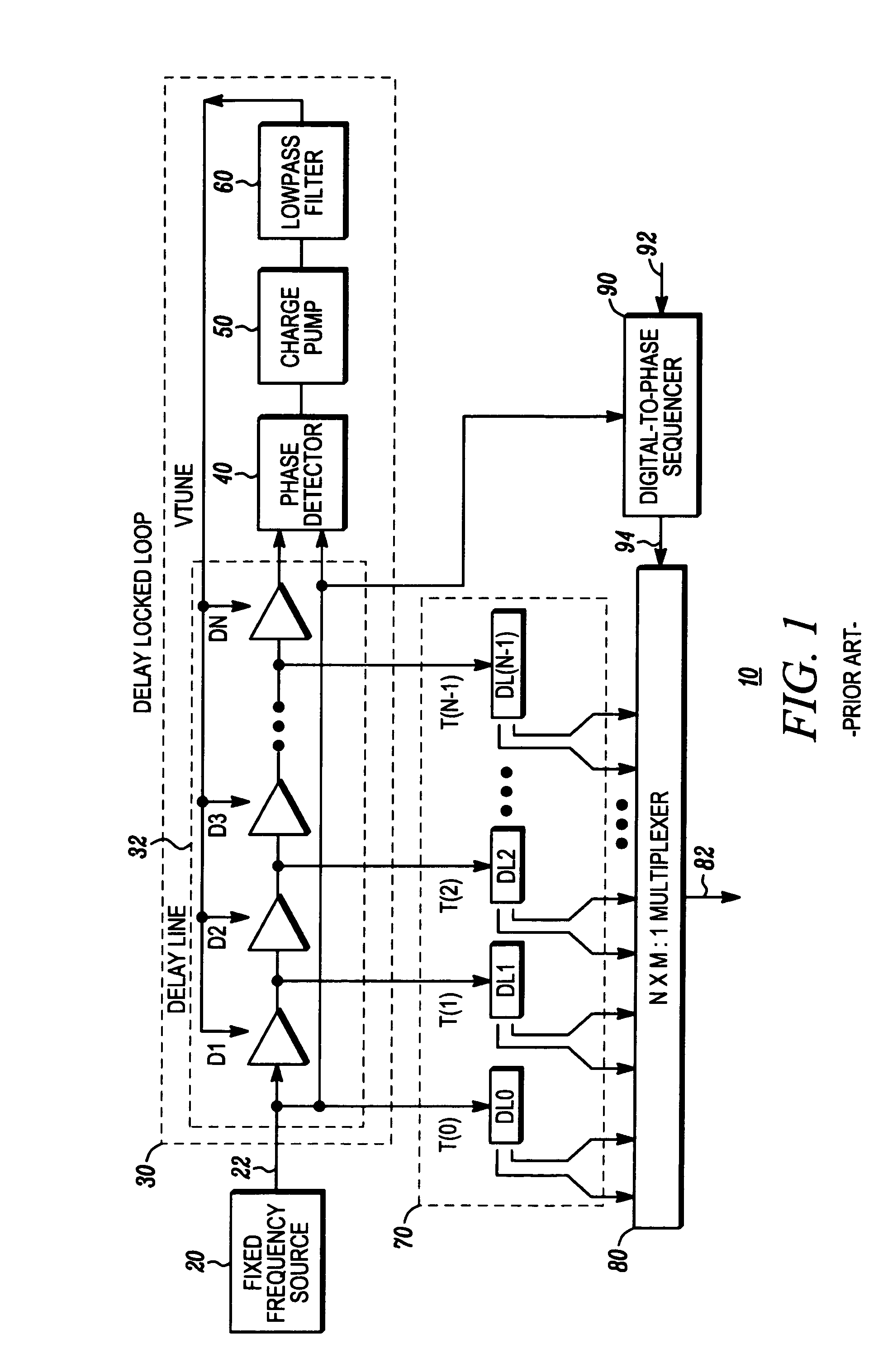
FIELD OF THE INVENTION [0001] The present invention relates generally to frequency synthesis and more specifically to a digital-to-phase converter that enables fine frequency selection using a variable delay cell. BACKGROUND OF THE INVENTION [0002] A number of devices, for instance mobile applications such as portable devices, require the use of a frequency synthesizer for operation. One such frequency synthesizer includes a digital-to-phase converter (DPC) having a delay-locked loop (DLL). FIG. 1 illustrates a block diagram of a prior art DPC 10 configuration for generating an output signal 82 at a desired frequency Fout. DPC 10 comprises a fixed frequency source 20 for generating a clock signal 22 having a frequency of Fclk. DPC 10 further comprises: a delay-locked loop 30 that includes a primary delay line 32 having N number of adjustable delay elements D1 through DN and a phase detector 40, a charge pump 50 and a low pass filter 60, which make up a stabilization circuit for DLL ...

Claims


Application Information

Patent Timeline
IPC IPC(8): H03L7/06
CPCH03K5/1504H03K2005/00032H03L7/16H03L7/0812H03L7/07H03L7/0818H03L7/0816
Inventor GABATO, MANUEL P. JR.CHARASKA, JOSEPH A.GAILUS, PAUL H.
Owner MOTOROLA SOLUTIONS INC
Learn More