Portable wireless unit

a portable wireless and antenna technology, applied in wireless communication, resonant antennas, differential interacting antenna combinations, etc., to achieve the effect of high antenna gain

Inactive Publication Date: 2009-03-12
PANASONIC CORP
View PDF4 Cites 13 Cited by
  • Summary
  • Abstract
  • Description
  • Claims
  • Application Information

AI Technical Summary

Benefits of technology

[0022]Furthermore, with arrangement of the antenna elements of the portable wireless unit according to the present invention, it is possible to gain a relatively high antenna gain even in the hand-held state.

Problems solved by technology

However, in the slide-type cellular telephone set described in Japanese Patent Laid-Open No. 2003-298695, although it is possible to realize reduction in size and enhancement in usability, there has been a problem with the configuration and position of the antenna in order to stably secure high quality antenna performance in either the extended or housed states.

Method used


Image

  • Portable wireless unit
  • Portable wireless unit
  • Portable wireless unit

Examples


embodiment

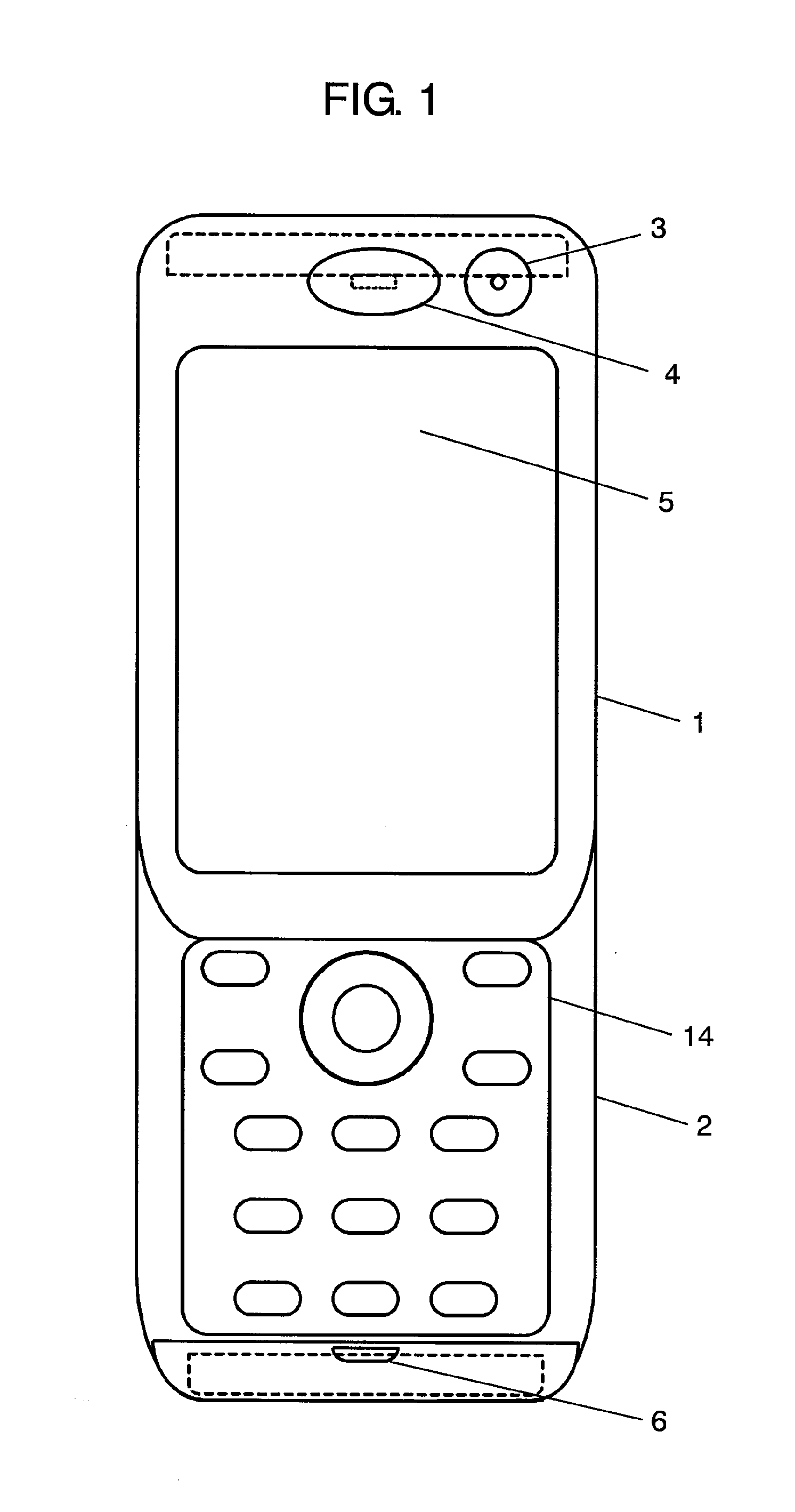
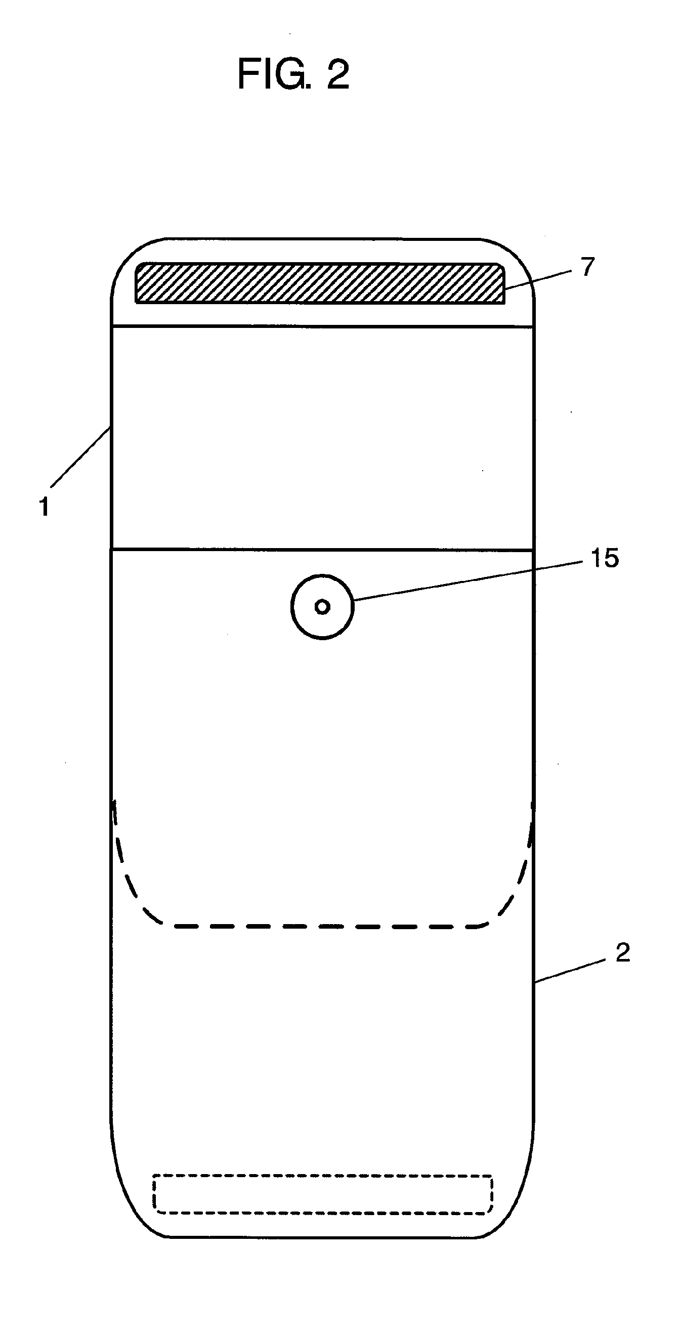
[0033]FIG. 1 is a front view of a slide-type portable wireless unit in one embodiment of the present invention, and FIG. 2 is a rear view of the slide-type portable wireless unit in the same embodiment of the present invention.

[0034]In FIG. 1, first case 1 comprises self-photographing camera 3 for photographing a user himself / herself, receiver 4 and display section 5, and second case 2 comprises microphone 6 and operating section 14. Further, although not shown, first antenna element is provided inside first case 1.

[0035]In FIG. 2, first case 1 comprises second antenna element 7 at its end along its short-side direction and opposite party photographing camera 15 for photographing a subject other than the user.

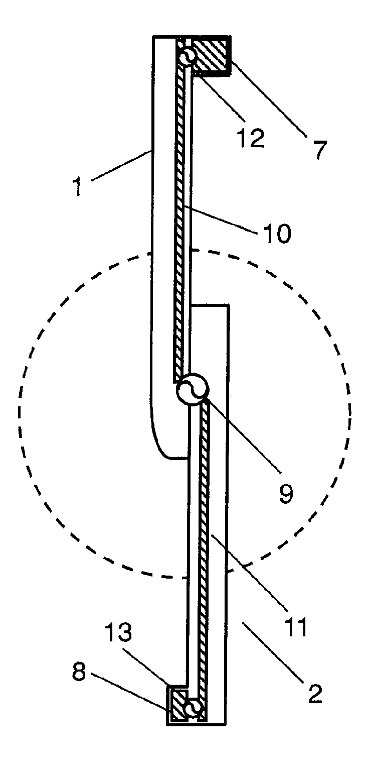
[0036]FIG. 3 is a front view of the slide-type portable wireless unit in a housed state in the same embodiment of the present invention. In FIG. 3, second case 2 comprises third antenna element 8 at its end along its short-side direction. Further, although not shown, a circuit ...


PUM


Abstract

A portable wireless unit having high antenna performance, which comprises: a first case having a first antenna element, a second antenna element and a second feeding section; a second case having a third antenna element, a third feeding section and a circuit board provided with a ground pattern; and a coupling section consisting of first and second electrically connected conductive coupling elements and coupling the first case and the second case to be extended and housed freely. The second coupling element is provided in the first case while being connected electrically with the first antenna element, the first coupling element is provided in the second case while being connected electrically with the first feeding section, and the first antenna element, the coupling section, and the ground pattern are operated as a dipole antenna.

Description

[0001]This Application is a U.S. National Phase Application of PCT International Application PCT / JP2005 / 020771.TECHNICAL FIELD[0002]The present invention relate to a configuration and positions of antennas inside a portable wireless unit, for example one having a slide-type structure, especially for securing stable communication quality in response to a used condition of the unit.BACKGROUND ART[0003]Among slide-type cellular telephone sets consisting of an upper case, a lower case and a coupling section, a conventionally known cellular telephone set is one having a configuration where an antenna is provided in the vicinity of the coupling section of the lowercase, and the antenna is extended associated with an operation to extend the case when the case is opened, and is housed associated with an operation to house the case when the case is housed. With such a configuration, since a trouble of extension / retraction of the antenna is saved and the antenna is extended without fail in us...

Claims


Application Information

Patent Timeline
Patent Type & Authority Applications(United States)
IPC IPC(8): H01Q3/24H01Q1/24H01Q1/48H01Q9/16H04B1/38H04B1/3822H04W88/02
CPCH01Q1/243H04M1/0235H01Q21/29H01Q9/16
Inventor SATO, KENICHITAKAHASHI, YUKINARIWATANABE, SATOSHI
Owner PANASONIC CORP
Why Eureka
Try Eureka