Electro-optic display device and method of driving the same

a display device and optical technology, applied in the direction of instruments, static indicating devices, etc., can solve the problems of changing the timing at which data signals are supplied, affecting the display quality of the epd device, and affecting the quality of the display, so as to prevent the deterioration of display quality and increase the supply time of scan signals

Inactive Publication Date: 2009-03-12
SAMSUNG ELECTRONICS CO LTD
View PDF6 Cites 13 Cited by
  • Summary
  • Abstract
  • Description
  • Claims
  • Application Information

AI Technical Summary

Benefits of technology

[0011]The present invention provides an EPD device that may be capable of increasing supplying time of scan signals during a refresh period to prevent deterioration of display quality, and a method of driving the EPD device.

Problems solved by technology

The scan signals may be distorted by RC delays of the gate lines, which may change the timing at which data signals are supplied.
As a result, the display quality of the EPD device may worsen.
However, when the time required to supply the scan signals during the refresh period decreases due to the RC delay of the scan signals, refreshing can be insufficiently accomplished, and therefore, an operation error, such as image sticking, may occur.

Method used


Image

  • Electro-optic display device and method of driving the same
  • Electro-optic display device and method of driving the same
  • Electro-optic display device and method of driving the same

Examples


Embodiment Construction

[0025]The invention is described more fully hereinafter with reference to the accompanying drawings, in which embodiments of the invention are shown. This invention may, however, be embodied in many different forms and should not be construed as limited to the embodiments set forth herein. Rather, these embodiments are provided so that this disclosure is thorough, and will fully convey the scope of the invention to those skilled in the art. In the drawings, the size and relative size of layers and regions may be exaggerated for clarity. Like reference numerals in the drawings denote like elements. Hereinafter, exemplary embodiments of the present invention will be described in more detail with reference to accompanying drawings.

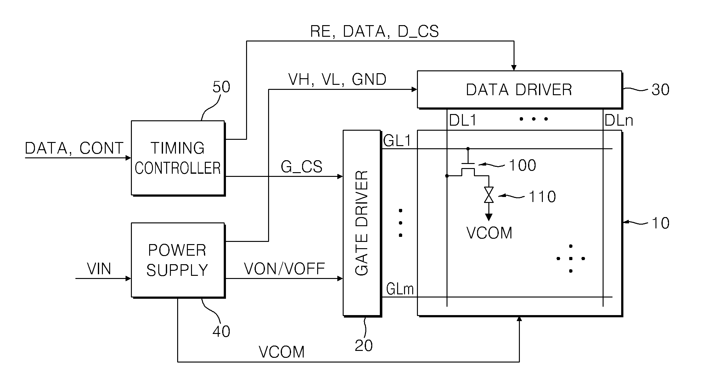
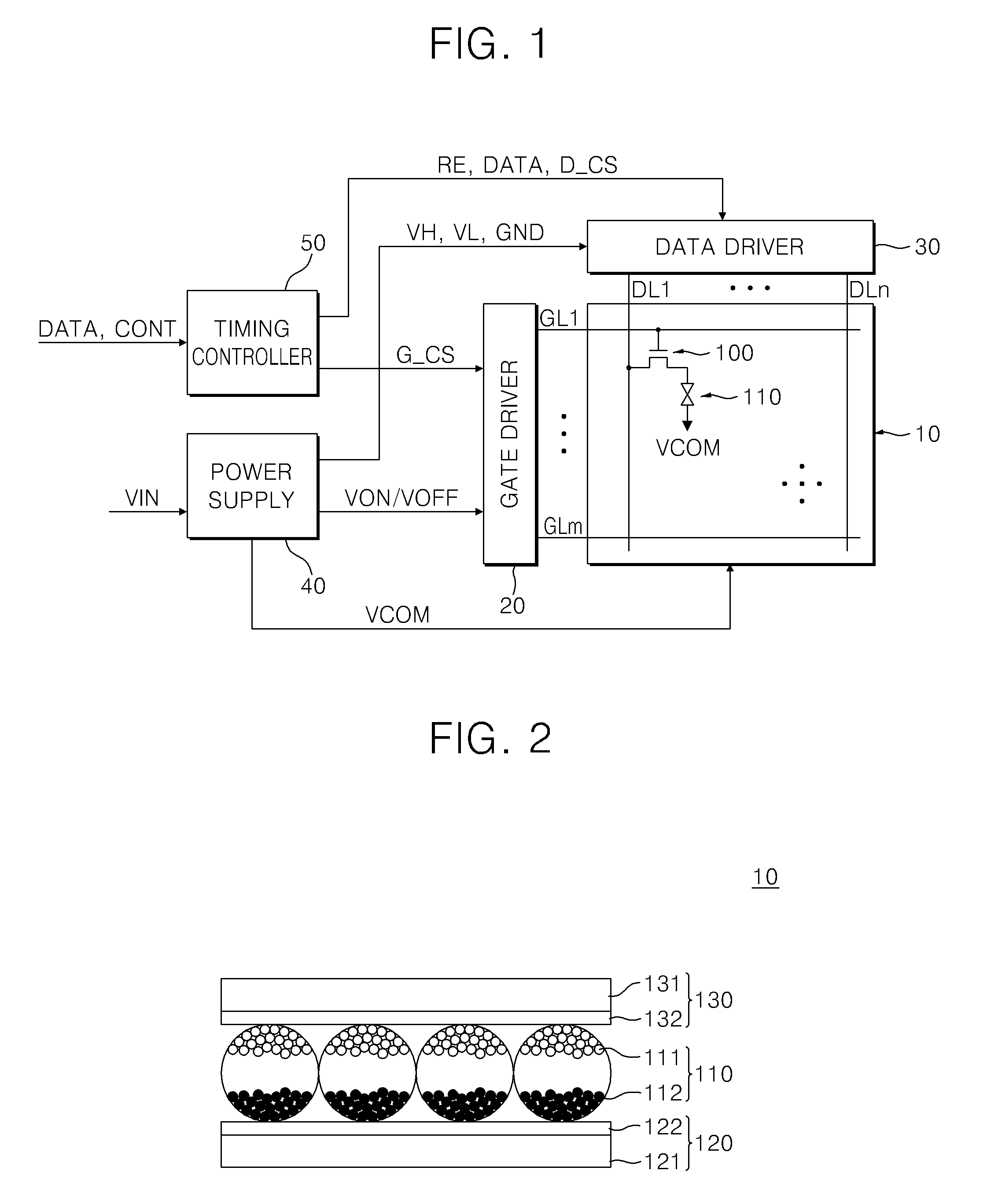
[0026]FIG. 1 is a block diagram of an EPD device according to an exemplary embodiment of the present invention, and FIG. 2 is a cross section view of an EPD panel shown in FIG. 1. It will be understood that when an element or layer is referred to as being “on...


PUM


Abstract

Disclosed is an electrophoretic display device including an electrophoretic display panel, a gate driver to supply a scan signal to a gate line of the electrophoretic display panel for a longer time during a refresh period than during a data output period, a data driver to supply at least one of a refresh voltage and a data voltage to a data line of the electrophoretic display panel, and a timing controller to supply a gate control signal and a data control signal to the gate driver and the data driver, respectively, and a method of driving the electrophoretic display device.

Description

CROSS-REFERENCE TO RELATED APPLICATION[0001]This application claims priority from and the benefit of Korean Patent Application No. 10-2007-0090426, filed on Sep. 6, 2007, which is hereby incorporated by reference for all purposes as if fully set forth herein.BACKGROUND OF THE INVENTION[0002]1. Field of the Invention[0003]The present invention relates to an electro-optic display device and a method of driving the same, and more particularly to an electrophoretic display device that may be capable of increasing a refresh time to improve display quality, and a method of driving the same.[0004]2. Discussion of the Background[0005]Electro-optic display devices include a liquid crystal display (LCD) devices, plasma display devices, organic light emitting display (OLED) devices, and electrophoretic display (EPD) devices. Recently, an electrophoretic display (EPD) device, which does not need a backlight assembly to display an image, has been widely developed. The EPD has many advantages suc...

Claims


Application Information

Patent Timeline
Patent Type & Authority Applications(United States)
IPC IPC(8): G09G3/34G09G3/20
CPCG09G3/344G09G2310/0267G09G2310/063G09G2330/021G09G2320/0209G09G2320/0223G09G2310/08
Inventor KIM, JONG-HEEPARK, CHEOL-WOO
Owner SAMSUNG ELECTRONICS CO LTD
Why Eureka
Try Eureka