Integrated force sensitive lens and software

a force sensitive lens and software technology, applied in the direction of instruments, measurement devices, speed/acceleration/shock measurement, etc., can solve the problems of dead spots, poor production yield, and further reduced clarity

Active Publication Date: 2009-03-12
APPLE INC
View PDF2 Cites 120 Cited by
  • Summary
  • Abstract
  • Description
  • Claims
  • Application Information

AI Technical Summary

Benefits of technology

[0036]Accordingly, it is an object of the present invention to optimize an alternative force sensor technology in order to provide a low-cost pressure sensitive touch sensitive display solution suitable for manufacturers of electronic devices such as POS, ATMs and terminals and, specifically, portable electronic devices such as cell phones, cameras and PDA and other mobile computing devices.

Problems solved by technology

The disadvantage of a resistive pad is that the resistive membrane material will wear out, initially resulting in further reduced clarity followed by dead spots.
In addition, the production yield is typically rather poor and the technology has a few disadvantages such as a fixed (non-user adjustable) actuation force and the light throughput through the resistive membranes is typically only around 70% to 75%, reducing display visibility.
Capacitive pads are relatively expensive to manufacture compared to resistive, and can only detect objects with sufficient capacitance.
Small objects, such as the end of a regular stylus or pen, do not have enough capacitance to ground or trans-capacitance to be detected by a capacitive touchpad.
This often leads to difficulties in implementing certain end-user features, such as handwriting recognition.
These devices work well, but are generally much too expensive for general applications.
Infra red light based displays work in a similar fashion, but this technology typically adds a large size and a high cost increase.
Despite the availability of the existing sensing technologies mentioned herein, the prior art has been unable to provide a low-cost sensor assembly / solution having sufficient sensitivity, surface robustness, accuracy and form factor.
While most commercially available piezoresistive force sensors are highly accurate, they typically are not very durable and are large and expensive with only a few available component suppliers globally.
Unfortunately FSR sensors have a much narrower range of sensitivity.
In addition, there are also new, not yet commercialized, force sensor materials that are based on nano technology.
These above-described characteristics make it difficult to design a differential-pressure touch pad assembly based on FSR technology.

Method used


Image

  • Integrated force sensitive lens and software
  • Integrated force sensitive lens and software
  • Integrated force sensitive lens and software

Examples


Embodiment Construction

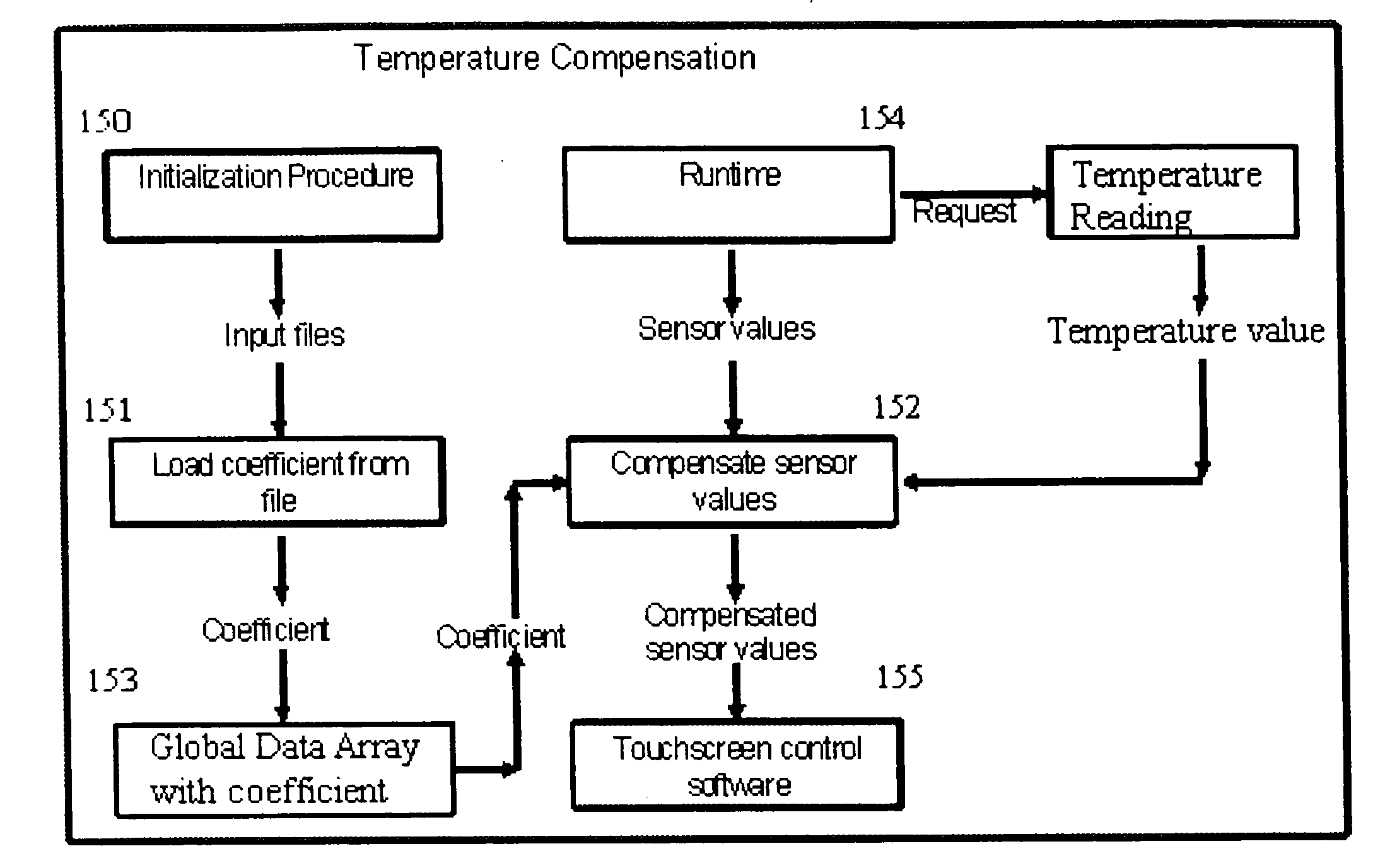
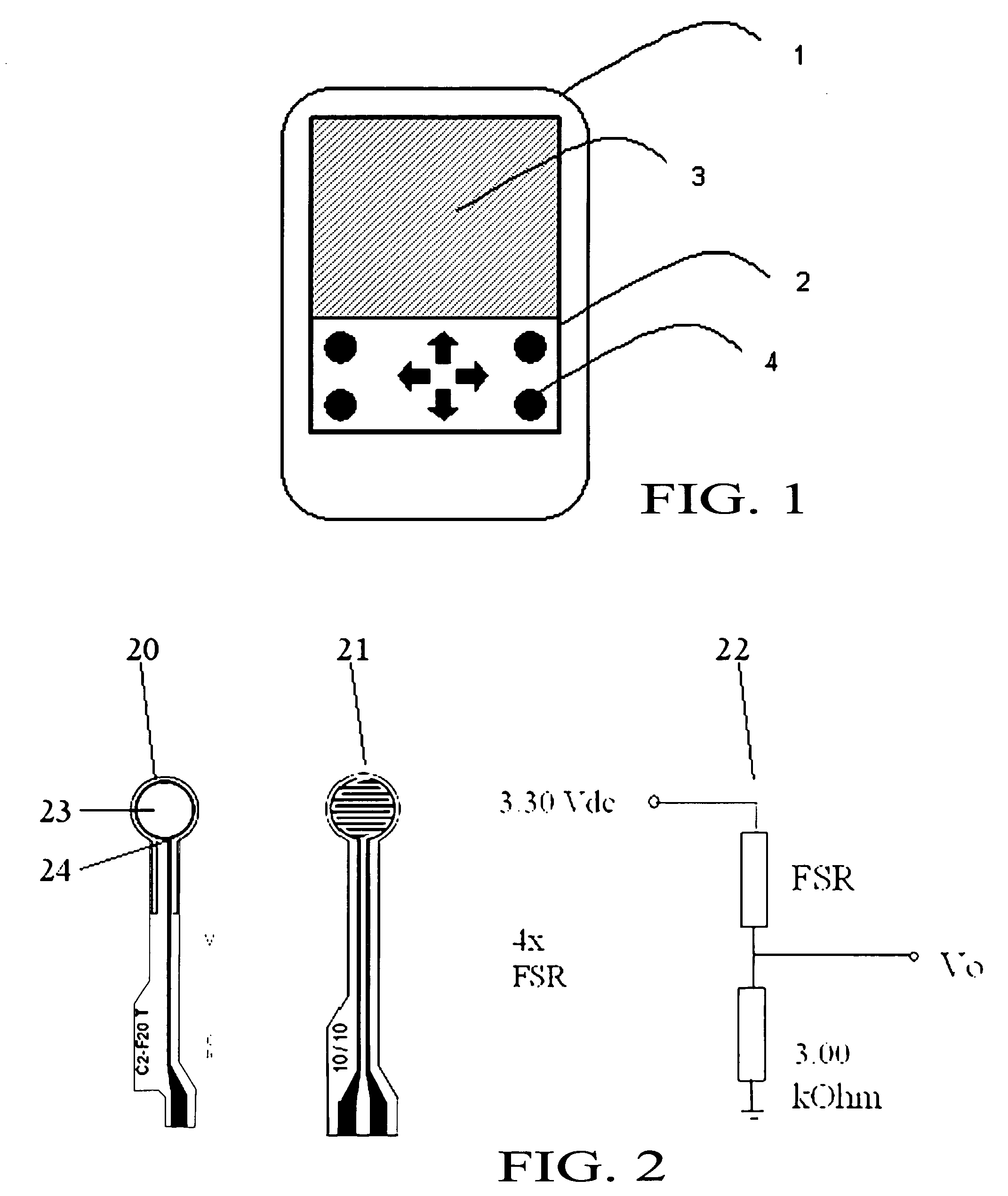
[0059]The present invention is a software compensation method that allows a touch sensitive display to be built using low-cost force sensors based on force sensing resistive material. The method is suitable for use in electronics devices such as cell phones, PDAs, desktop phones, tablets, copy machines, or any other devices that use differential-pressure touch sensitive displays or panels including LCD, Organic Light-Emitting Diode (OLED) display screens or touch pad / touch lens systems. The present method is herein described in the context of a mechanical differential-pressure touch screen system such as illustrated in FIG. 1 that uses a plurality of force sensors (such as, for example, four) differentially-mounted sensors 7 beneath it all connected to the electronic device 1 processor, as disclosed in International application no PCT / US2007 / 019606 filed 7 Sep. 2007, which application is herein incorporated by reference in its entirety.

[0060]FIG. 7 is a block diagram illustrating th...


PUM


Abstract

A software compensation method that allows a touch sensitive display to be built using low-cost FSR force sensors The compensation method comprises an array of functional compensation modules including filtering, voltage conversion, temperature compensation, humidity compensation, sensor calibration, sensor reading linearization, auto calibration, positioning determination and finally end-user and mechanical calibration. The array of compensation modules can bring system accuracy from a non-compensated average positioning error in the 25% to 50% range, down to aN end-user acceptable range of 0% to 5%. The increased positioning accuracy makes it possible to use FSRs as opposed to traditional piezoresistive based touch screen sensors.

Description

CROSS-REFERENCE TO RELATED APPLICATION(S)[0001]The present application is a continuation-in-part of International application no PCT / US2007 / 019606 filed 7 Sep. 2007, which designates the United States.BACKGROUND OF THE INVENTION[0002](1) Field of the Invention[0003]The present invention relates to input devices for electronics and, more particularly, to a touch sensitive input panel or display with small form factor especially suited for use in cellular phones and personal digital assistants (PDAs), PC Tablets, as well as laptops, PCs, office equipment, medical equipment, or any other device that uses touch sensitive displays or panels.[0004](2) Description of Prior Art[0005]Touch screens are being deployed in an increasing number of products using an array of several types of technology. Market analysts predict that in the mobile telephony market, touch screens will increase from less then 10% penetration to more then 50% penetration by 2010, assuming the cost of these touch screen...

Claims


Application Information

Patent Timeline
Patent Type & Authority Applications(United States)
IPC IPC(8): G06F3/041G06F19/00
CPCG06F3/0418G06F3/0414
Inventor MOLNE, ANDERS L.CARSANARO, JOSEPHLEINONEN, TONIKLIMOV, KONSTANTIN
Owner APPLE INC
Why Eureka
Try Eureka